note: originally posted
 I am a huge Baofeng UV-5RA handheld radio fan! Yes, it is a Ham Radio, but it is also much, much more and I love the little radio. It is a dynamo! The radio is a great size, packed full of features, reliable, and more than anything else EXTREMELY affordable. You can read more about my review of the Baofeng UV-5R radio here < UV-5RA review >. This post is dedicated to the ExpertPower XP-771 Elite 14.5-Inch Dual Band Antenna 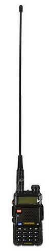 (144/430Mhz U/V SMA-F).
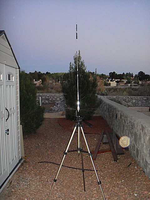
The antenna that comes with the unit is the typical “stubby” but works just fine. It is solid, sturdy and will do the job. However, for the frequency ranges of the UV-5R radio I wanted an appropriate sized antenna for better overall operation (range of reception and transmission). To fit that requirement I chose the ExpertPower® 14.5″ Dual Band Two-way Radio Antenna SMA-Female.
The improved gain performance results are noteworthy for a little handheld: 2.15dBi (144-146 MHz), 3.5dBi (430-440 MHz).
This antenna is very sturdy and works as advertised. And for $8.55 at the time I originally purchased it, it is hard to beat. It will run you about $10 – $12 now up on Amazon. Search hard, you might find a better deal, especially for a “quantity” purchase or group buy.
I will only use the stubby antenna when the longer antenna would get in the way, or when I purposely want very short ranges. Yes, there are times when I would want to keep operational range to a minimum. Think OpSec (Operational Security). Some folks (purists) might correctly refer to that as ComSec (Communications Security). But when the extra range is needed (reception and transmission) I will use the 14.5” antenna. Also, there is a marked improvement in the quality of reception at any range when using this longer antenna. I am not sure if it is the additional length or simply a better quality antenna, maybe both.
Some Tech Specs:
 Frequency Range: 144-146, 430-440 MHz
- VSWR: less than 1.5
- Gain: 2.15dBi (144-146 MHz), 3.5dBi (430-440 MHz)
- Maximum Power Input-watts: 50 W
- Height: 14.4 inches
- Connector: SMA-Female

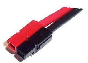
Antenna Flaw –
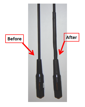
There is an inherent flaw to this antenna. However, the flaw is not unique to this particular antenna, it is present in all of the 14.5″ antennas I researched. If you look at the picture to the right, see the red arrow? It points to the area 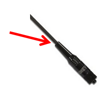 where the antenna itself (stick) goes into the antenna base. There is a very small gap around the antenna in that spot. OK, maybe “flaw” is a little excessive, but, there is a problem with all antennas like this that could turn into a larger problem down the line. But, not to worry…I have a fix for it. I will explain how to correct this problem and strengthen the antenna at the same time.
Le t me explain the problem first. If it were raining, rain could roll down the antenna and get into the antenna base and then make its way to the point where the antenna connects to the radio. The moisture itself could enter the radio or just collect in the base itself and eventually corrode the metal potentially causing a connection/operations problem.
But it is a relatively easy fix in my opinion. And there is a “bonus feature” when you are done with with very minor fix, a stronger antenna less prone to fail at that inherent weak point.
To implement the “fix” do the following…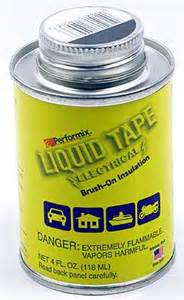
Step #1 – Go to your local hardware store and buy:
- Performix Liquid Tape – Electrical
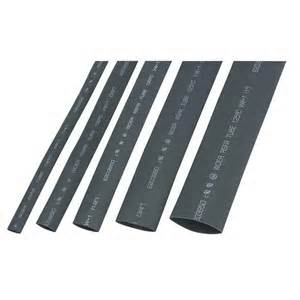
- 1/2″ electrical shrink wrap, 3″ lengths are fine.

- 5/8″ electrical shrink wrap, at least 3″ long but preferably 4″ – 5″ in length. Fastenall carries longer lengths of shrink wrap at very good prices.
- Option, buy only 1/2″ electrical shrink wrap, but in 5″ lengths. This won’t work with a single piece of 5/8″ shrink wrap, it simply won’t shrink down enough.
- If you don’t already own one, buy a long-handled Bic lighter.
Step #2 – With a toothpick apply a very small amount of liquid tape to the gap between the antenna “stick” and the antenna base.  (see the read arrow in the above picture pointing at that gap.) Use the toothpick to get the liquid tape
 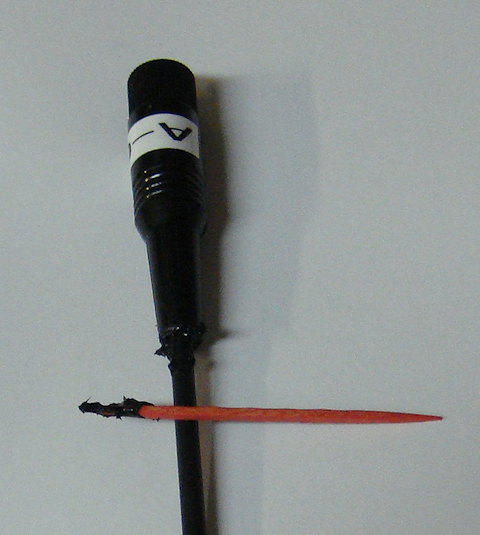 from the can and then use it to push a small amount of the liquid into the gap all the way around. You are not trying to fill up the gap all the way to the base. Just put enough to create a “gasket effect” in the gap.
Clean up the excess Liquid Tape off the antenna. Only worry about it being “reasonably” cleaned up. This will get covered up with shrink wrap and no one will see it when you’re done.

Now, put the antenna down and leave it alone for a day. This will allow it to dry completely. Don’t get impatient, allow it to thoroughly dry. And do yourself a favor…don’t set it where your dog or toddler will find it and chew it to pieces.
option #1
Step #3 –You now have two options, choose the one that fits the parts you have on-hand.
Option #1 : While you are waiting for the liquid tape to dry, get your shrink wrap out. Cut one piece of the 1/2″ shrink wrap to a length of 2″ – 2-1/2″. Leave the 5/8″ piece at least 3″ in length.
Option #2 : You will use a single piece of 1/2″ electrical shrink wrap that is 5″ – 6″ in length. You don’t need to do anything to prep this option.
Step #4 – You’ve allowed the liquid tape to dry for a day. You also have prepped your shrink wrap based on your “option” choice and you are ready to go. You kept the Bic lighter out of the hands of your 4-year old, so your house is still standing. You are now ready to put the shrink wrap on.
Step #5 – OPTION #1 :Take the 1/2″ piece of shrink wrap that you cut to 2″ – 2-1/2″ in length and slide it over the  knob of the antenna. Move it all the way to the base of the antenna. Push it, and work it down, so the shrink wrap goes slightly over the expanding base of the antenna. Using the long handled Bic lighter heat the shrink wrap in-place and allow it to cool. DO NOT OVER HEAT THE SHRINK WRAP! If you do, you can damage the antenna. You want to heat the shrink wrap just enough to shrink it up solidly in contact with the base and the antenna stick itself, especially where the antenna enters the base.
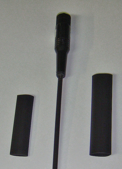
Once the first piece of shrink wrap is cooled down take the longer 5/8″ piece of shrink wrap and  slide it over the antenna knob as well. When you get to the antenna base keep sliding the shrink wrap over the expanding base until it won’t go any further. It should slide on well past (or lower) than the first piece of shrink wrap that you put on. There are small ridges on the antenna base; you should be able to work the shrink wrap over the first ridge line (see the picture to the right).
You will now heat this piece of shrink wrap as well. But, you may have to hold the shrink wrap in-place with one hand to ensure that it stays as low on the antenna base as possible. Make sure it continues to cover the first piece of shrink wrap while you heat it.You want the double-layer of shrink wrap for bet protection.
Make sure you have a nice “snug” shrink against the antenna stick towards the top of the antenna. DO NOT OVER HEAT THE SHRINK WRAP! If you do, you can damage the antenna. You want to heat the shrink wrap just enough to shrink up solidly in contact with the base and antenna stick.
OPTION #2 : If you are using a single piece of 1/2″ electrical shrink wrap that is 4″ – 5″ in length, you will slide it over the knob of the antenna. Move it all the way to the base of the antenna. Push it, and work it down, so the shrink wrap goes as much over the over the expanding base of the antenna as possible. Using the long-handled Bic lighter heat the shrink wrap in-place and allow it to cool.
DO NOT OVER HEAT THE SHRINK WRAP! If you do, you can damage the antenna. You want to heat the shrink wrap just enough to shrink it up solidly in contact with the base and the antenna itself, especially where the antenna stick enters the base. Pay particular attention to “rolling” the shrink wrap onto the antenna stick to make a really good tight wrap. You don’t want gaps at the top where the shrink wrap ends on the antenna stick. Roll it around while it is hot to ensure it is in solid, gap-free, contact with the antenna stick. (see picture below) Yes, I roll it with my fingers, but it may be too hot for you. Use gloves if you need to.
Step #6 – If the end of the shrink wrap, opposite of the antenna base, still appears a little “loose” allow it to cool completely. Once it is cool, then try applying some more heat to it to finish the shrinking process. But remember DO NOT overheat the shrink wrap or antenna while doing this. I found after doing three antennas, that once the heat shrink is sufficiently heated and close to completely shrunk up against the antenna stick and base, that I roll in between my fingers tightly pressing it to the antenna stick. Yes, it is a little warm but not uncomfortable or painful. Disclaimer: Yes, its hot. So be careful not to burn yourself. Use gloves if you need to protect your fingers.
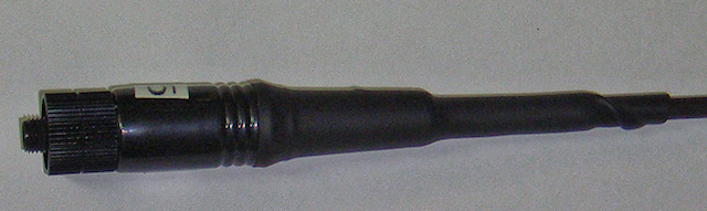
completed option #1 view
completed option #2 view
Now that you have completed the “fix” you have a virtually waterproof antenna abse. And remember the “bonus” I spoke of? By adding this fix you also have a much stronger antenna that is far less likely to fail at the point where the antenna stick enters the antenna base. It is at that point where most antennas fail during their lifetime.
2009 - 2020 Copyright © AHTrimble.com ~ All rights reserved
No reproduction or other use of this content
without expressed written permission from AHTrimble.com
See Content Use Policy for more information.