My “Power-Box” Project – Part #1

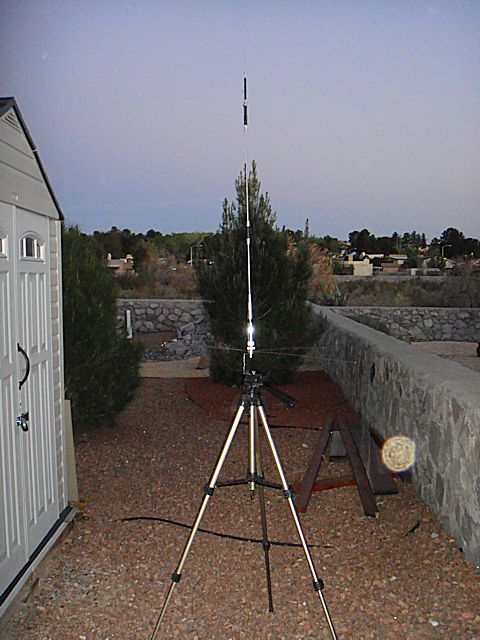
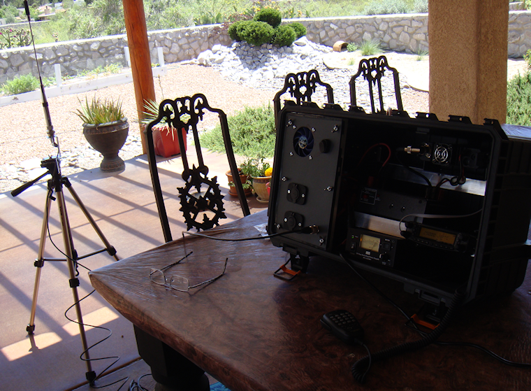
I built my “ham-in-the-box” radio kit that contains my Yaesu FT-8900R for use during emergencies, disasters and anytime there Ham-in-the-box mobile ham radio set-up with Yaesu FT-8900ris a “grid-down” situation. And it works like a charm, I love it. Read more about it here < click here to read more >.And as long as there was normal 110 vAC utility power then I was all set because the unit has a MFJ Enterprises Inc. MFJ-4230MV AC power supply built into it. But what about Ham In The Box - MFJ Enterprises Inc. MFJ-4230MV COMPACT SWITCHwhen the power goes off? Yeah, of course I accounted for the possibility, and this article will address the “power out” situation.

One thing that is a true “unknown” when the power goes out in emergencies and disasters is, how long will the power stay off. I tried to get a good feel for it but just couldn’t come up with a valid time estimate. That being the case I just counted on it staying off…till it came back on. Yes, I am serious. So that led me to the easy answer for alternative power, solar.

I know that for some folks in some areas of the country that solar is a limited choice. And I can appreciate that so I tried to build into the system little redundancy that might help overcome the solar-challenges that people have in some parts of the country and world. Here in the southwest it is not a problem at all so it is a perfect solution for me.

So, as always, let’s define the mission for this alternative power source. The unit must be able to:

“Provide sufficient power to allow the use of the emergency radio kit for at least 40% of any given 24-hour period. During which transmission power usage will be approximately 20% of that time period.”

Requirements & Restrictions:

  1. Had to be very reliable.
  2. Had to come from readily replaceable parts.
  3. Had to have at least levels of redundancy.
  4. Had to be usable stand-alone or in conjunction with other equipment.
  5. Should be transferable to other equipment as power source.
  6. Should be able to charge other electronic components via cigarette lighter and USB ports.

In easier to understand terms: I want my radio to be operational for 6 hours per day, of which about 70 – 80 Yaesu FT-8900r Quad-Band Ham Radiominutes will be time when I am actually transmitting. That is pretty aggressive for transmitting time. My Yaesu FT-8900R uses a maximum of 8.5A during transmission. So I figure a 60 AH (ampere hour) rated AGM battery should handle the load with a fairly decent margin of error. So I went with a 100 AH AGM deep cycle battery to allow myself plenty of wiggle room. But that isn’t all.

One of the problems are those times when usage exceeds what your expectations were. I really want to make sure that I have enough “reserve” power to handle the radio usage when the demand is at its peak, such as the early stages of a disaster or during an “incident within an incident” occurrence. I could have simply bought a higher rated AH battery. But that is putting all my eggs in one basket; if that battery takes a dump then all of my power is gone. Hence, the whole concept of redundancy, two separate battery banks; 1) the 100 AH battery, 2) the other is 36 AH of AGM battery power (two x 18 AH batteries). The two separate battery banks are not connected.

The large 100 AH battery is an Energizer AGM battery, Model: 31A 100 Amp HourMAX. And that bad boy is big and heavy. I recharge it using a portable, folding 60w solar panel set-up. The charger controller unit has a “low voltage disconnect” built in. That unit prevents the battery from becoming too discharged and thus damaging the batteries. But I use it to trigger a relay that trips when the batteries become too discharged. And when that relay trips it switches over to the other set of 
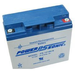
batteries (two 18 AH PowerSonic AGM batteries).

When that switchover is made the larger 100 AH battery can then recharge without any drain on the battery. Once it comes back up to a full charge then the relay kicks again bringing the 100 AH battery back online. That also means that the smaller battery bank goes off-line. And to keep those two 18 AH batteries charged up I have another dual 60w solar panel set-up.

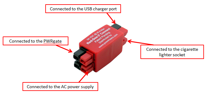
But it doesn’t end there. Remember that the Ham-In-The-Box has a PWRgate built into it? Yup, that is the unit that Ham In The Box - Super PWRgate PG40S by West Mountain Radioswitches between AC power and battery back-up. That makes it nice if the regular 120 vAC utility power goes out it switches automatically over to battery back-up. Sweet, eh? But there is a bonus to the PWRgate…it is also a battery charger when on AC power. So it will maintain the 100 AH main battery anytime AC power is available.

So let’s review the power options for the Ham-In-The-Box and Power-Box combination:

Option #1 – There is normal utility company 120 vAC power available. The Ham-In-The-Box runs off that power and keeps the 100 AH primary battery fully charged. If the AC power goes off the Ham-In-The-Box automatically switches over to the Power-Box.Honda EU2000i Generator

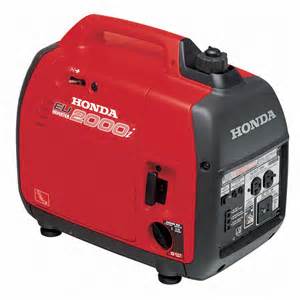
Option #2 – I can hook up my Honda EU-2000i which then supplies AC power to the Ham-In-The-Box and keeps the 100 AH primary battery fully charged.. If the Honda shuts down the Ham-In-The-Box automatically switches over to the Power-Box.

Option #3 – The Ham-In-The-Box is running off of the primary 100 AH battery in the 
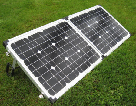
Power-Box. A dual panel 60w solar system is charging the 100 AH primary battery. Also, a dual panel 60w solar system is charging the two back-up 18 AH batteries. If the primary battery drops below an operational charge (goes dead for operational purposes) the system automatically switches over to the Power-Box back-up batteries.

Option #4 – The Ham-In-The-Box is running off of the Power-Box back-up batteries. A dual panel 60w solar system (or a single 30W panel) is charging those back-up batteries. Another dual panel 60w solar system is charging the 100 AH primary battery bringing it back up to full charge. Once it is up to full charge the Power-Box switches back over to using the primary 100 AH battery. And the Power-Box back-up batteries are then being charged back up to a full charge by the dual panel 60w or single 30W panel solar system.Schumacher SC-10030A battery charger to

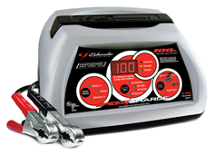
Option #5 – I can use the Honda EU2000i with the Schumacher SC-10030A battery charger to recharge the 100 AH primary battery (approximately 2 – 3 hours) while the Power-Box back-up batteries are supplying power to the Ham-In-The-Box.

Option #6 – I can use the Honda EU2000i’s 12vDC outlet and plug a cord directly into either solar panel input port on the box and recharge the batteries directly.

I am sure there are more options that would work with this but these are the ones that make the most operational sense to me for an emergency, disaster and “grid-down” situation. But let’s now look at Power-Box and its design and components.

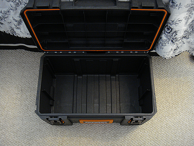
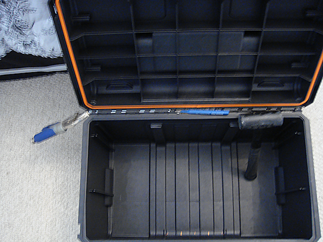
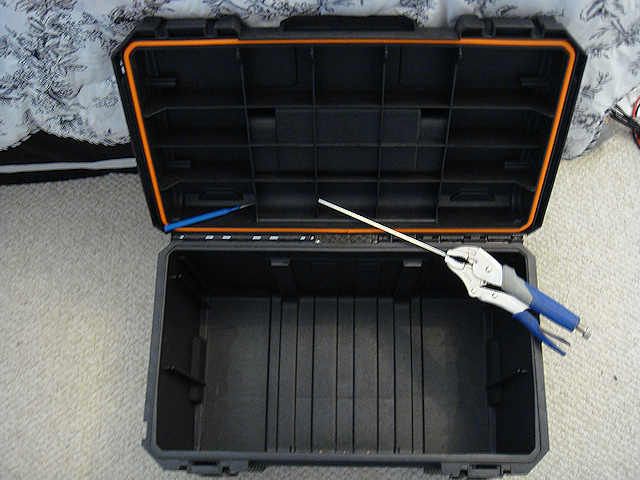
Let’s go over the actual box first. I chose the Rigid Professional Tool Storage System. This “system” is a group Rigid Professional Tool Storage System 22" Too Boxof very sturdy tool boxes designed to work together. The base unit is the Mobile Gear Cart. It is the box that all the other pieces ride on. It measures out at: 22” x 18” x 19”. That is plenty large enough for holding all three batteries. And as an added bonus, the storage box has wheels which are extremely important since the batteries are heavy. The storage box is also heavy plastic making it pretty much dirt and watertight.

Now that we have the actual storage box, I will list the batteries that I choose:Energizer AGM battery, Model: 31A 100 Amp Hour

  • Battery #1 – Energizer Max AGM. 100 Ampere Hour, measures 13” x 7” x 9.5” and weighs in at an impressive 60 – 65 lbs (+/-).
  • Battery #2 & #3 – Powersonic Battery TY12-18. Each battery is an 18 Ampere Hour, measures 7” x 3” x 6.75” and each weighs 13 pounds.

The combined weight of the batteries alone comes in at 85 – 90 pounds. So far the storage box can handle the weight just fine. Yeah, you are going to have to have help lifting it into the truck or SUV. That’s what friends are for 😉

For recharging the primary 100 AH battery here is the list of components:

  • Dual 30w solar panels set-up as a folding, portable kit. (Glowtech System)
  • Morningstar SL-20L-12V charge controller.

I went with a system from Discount Solar. The price was $135 and that included shipping. The portable system comes with a charge controller but not the MorningStar SL-20L-12V. The relay disconnect is integral to the system I am building so I simply by-passed the charge controller that came with the system. I did leave the charge controller on the unit for flexibility. I switched over all the internal wire connections to Anderson PowerPoles to be compatible with everything else I have. I will give detailed steps a little later, for now I am just listing the parts.

For recharging the back-up 18 AH batteries here is the list of components:

This is a straight up system purchased from GoalZero a couple of years ago. The equipment is top-notch, high-quality stuff to be sure. Unfortunately you are paying for the GoalZero name. Don’t fall for it. At the end of this series I will do a Q&A (FAQ) section and provide a tested alternative system that is a whole lot less money. But for now I am going with what I have on-hand. And I did the same thing with this GoalZero set-up and the wiring connection, I switched them all over to Anderson PowerPoles to be compatible with everything else I have. I will give detailed steps a little later, for now I am just listing the parts.


2009 - 2020 Copyright © AHTrimble.com ~ All rights reserved
No reproduction or other use of this content 
without expressed written permission from AHTrimble.com
See Content Use Policy for more information.

My “Ham-In-The-Box” Project – Yaesu FT-8900R Go-Box – Part #3

Ham in the box, ham-in-the-box, field deployable ham radio, ham radio in teh fieldnote: This article first appeared in May 2015.

In Part #1 (posted day before yesterday) of this series I covered the mission of this Ham-In-The-Box project, requirements and limitations, and the initial challenges that I faced. I also outlined each piece of equipment that would make up the final product.

In Part #2 (posted yesterday) of this series I started relating the actual step-by-step build process. I went from prepping the box itself, building the internal frame and getting all the way through installing the remote head to the radio.

In this post I will finish out the building of this project. It was a great project, took much longer than I expected, I picked up some valuable experience and knowledge, and I learned another great lesson along the way. But when it was all over, the project functioned exactly as designed!

Just a reminder of the mission of this project –

To be able to rapidly field deploy a Ham radio, for which I am licensed to use, in the event of any emergency while maintaining a secure and protective storage environment.

~ The “Build” (continued) ~

Step 9 –

This was one of the weirdest parts that I fabricated, the front panel frame. I wanted the frame sturdy, rigid but not heavy. And I couldn’t have it too large or it would get in the way of the fan and other accessories. So I went with 3/4” angle aluminum. While I was measuring the different pieces I found there was a small “notch” or pocket in toolbox’s corner that a piece of the aluminum fit into perfectly. So I took advantage of that and used it to hold the frame in-place and semi-attached to the toolbox. The side benefit was making the whole structural frame kind of like a part of the toolbox without really attaching it. So that is the reason for the one slightly longer side to the frame. If you are looking at the box with the lid opening towards you, the longer leg would go into the notch on the front left side right under the “lip” of the toolbox. I used rivets to secure the pieces.

front view of frame


Then I was working on the solution to attaching the front panel to the frame. I really wanted to be able to remove the front panel to access the components underneath. But exactly how to do that securely while maintaining convenience was a bit difficult to figure out. Then it dawned on me to use JB Weld to bond the bolt heads to the frame. Then it was a matter of drilling out the holes in the front panel to match the bolts.

rear view of frame


Note: The 2″ notch in the front panel frame was not intentional. When I was laying out the frame and the front panel I forgot the “offset” from the left side of the box and didn’t line-up the fan to the frame correctly. I had to cut the notch so the fan wouldn’t interfere with the frame, or visa-versa.

Step 10 –

I really wanted the front panel to look sharp as well as be functional and lightweight. I went shopping for possible materials and found everything expensive. Then a moment of inspiration! I headed off to the local Goodwill and purchased a used VCR with a metal case. The metal that the case was made of was sturdy steel, thin, and a nicely painted black with a bit of texture to it. Perfect!

front


rear


Note: I used masking tape place over the metal to help prevent damage while drilling the hole. I also used a good hole-punch and gave it a sharp whack with a hammer to make a serious starter hole so the drill wouldn’t “wander” when I was starting the hole.

I used Gorilla Tape to finish off the edges and give it a slightly cleaner look than rough-cut exposed edges. Yes, I like Gorilla Tape better than Duct Tape.

The fan had to be positioned directly over the PWRgate to blow air directly at its heat sink, so I had little choice to its location on the front panel. Then I mounted a switch next to it. I figured there would be times when the air movement might not be required so why not have the capability to turn the fan off. When I attached the fan to the back of the panel I used Gorilla Tape around the hole to create a bit of a “stand-off” from the metal panel to make sure the fan blades didn’t come into contact with the metal. The tape also works a little like a rubber washer absorbing vibration from the fan. To cut the hole for the fan I used a hole saw with the correct diameter cutter. Using a hole saw made a much cleaner hole than other methods. The switch hole was drilled out with a regular drill bit as per the instructions that came with the switch.

The next requirement was the “through the case” antenna lead connector. I thought at first about just having it loose and connect it. But then I thought I wanted the box to look as professional as possible so I mounted it on the front panel. The hole for the male-to-male connector was drilled out with a regular drill bit.

Then I positioned my remaining two accessories; the cigarette lighter socket and the USB charging port. I decided to mount cigarette lighter socket lowest on the front panel thinking it might have the heavier item plugged into it. Mounting it lower on the panel might make less weight/torque on panel. The other socket would be for charging USB devices. I figured they would be lighter weight and less of a Wight/torque problem. The larger holes for the cases were cut using a hole saw which made a much cleaner hole than other methods. I use my hole punch to punch a hole through the case and then screwed in the sheet metal screws through the panel.

Step 11 –

Front panel wiring. This is where I struggled just a bit. I am not particularly good with making Anderson Powerpole connections with heavy or real lightweight wire. And my fears proved to be true. I also had to figure out how to distribute the power as well.

I wanted the cigarette lighter socket and the USB charger ports to only be available when working off of shore power not battery power. When on battery power I only want to use valuable battery amps for the radio and cooling fan. So the power to those two accessories had to be “distributed” before sending the power to the PWRgate. For that job I originally choose a Powerwerx Red-Dee-2 Connector 4-way (PS4) connector in a star pattern.

But when I installed it in the box the wires just were a mess and it was difficult to get them into place. So I looked again and saw the same identification for a different part that made a lot more sense. It worked just fine.

I used fuses for each of the cigarette lighter socket and the USB charger port to make sure I protected any devices that I might be using/charging. I chose a simple 15amp glass fuse.

I took this picture to make it easier to see how the front panel was wired. I swapped out the Powerwerx distribution part after the picture was taken. The two heavy 10gauge wires carry the power from the PWRgate to the battery booster. That ensures that the fan will always have power, even if on battery power.

Note: The red tape on the fuse wires is just a visual reminder that they are “hot” wires. I did that since the fuse wires are black.

This is what it looks liked when I put the heavier wires together with their Powerpoles connected. I put zip ties on them to make the wires easier to manage and reduce tension and torque as the wires were being handled.  Don’t get confused, the red/black pair doesn’t attach to the distribution device, it goes from the PWRgate to the batter booster so it always has power. The wires going to the cigarette lighter socket and the USB charger port only have power with on shore power.

Step 12 –

So with all the wiring done it was time to get the multimeter out and check it. When it comes to something like this I check things in stages, only hooking one device up at a time to power. So the only thing that I turned on initially was the AC power supply. I checked its output with the multimeter and it was fine.

Then I plugged in the power supply to the Powerwerx 4-way. Each output worked fine. Then hooked up each of the accessory ports (cigarette & USB), they worked fine. Then the big test, I hooked up the PWRgate. It came on, the right lights were on so all was good. Then the fan test, hit the switch and the fan didn’t work. Turns out I had the wires hooked up wrong. Here is the switch and the wiring diagram.

KC HiLiTES Oval Rocker Switch with Red LED Indicator 30 Amp – Black – KC #3116

KC HiLiTES Oval Rocker Switch with Green LED Indicator 30 Amp - Black - KC #3116KC HiLiTES Oval Rocker Switch with Green LED Indicator 30 Amp - Black - KC #3116 wiring diagramNext to get hooked up and tested was the battery booster. All was fine, the right lights were on and all was good. I had to laugh though, when I turned on the AC power supply to make the next connection the battery boost gave the “low voltage” warning signal. Surprised me.

Now the big test, the radio. But before I tested the radio I had to hook up an antenna. You must do that or risk burning up your radio. So I got out my rig. You might remember that rig from my article Antenna Stand and Ground Plane for the Yaesu FT-8900R <click here to read article>

TRAM 1465 Land Mobile Base Ground Plane KitI ensured that the fuse in the radio “hot” wire was good, it was. I hooked the radio up to the battery booster, then turned on the AC power supply. All was good, no smell of burnt wiring. Then I hit the button on the Yaesu FT-8900R to power it up. Nothing, dead as a door nail. I turned off the power, turned it back on, hit the button the radio…nothing.

One time before I had screwed-up the remote head cable which made it not power up. I figured I had done the same thing here. But to get to the cable I had to remove the radio. So I took out the radio and checked the cable, all seemed fine. So I thought I would test the radio before installing it back in the box. Same thing, still dead. I was beginning to worry that I had fried my radio somehow. No………..just me being and idiot. I was pushing the wrong button. I pushed the correct button and the radio powered on. I installed it back in the box, hooked everything back up and right the right button. Bingo! Up it comes and I started scanning and listened to folks having a conversation.

Here is the completed product –

This………

Rigid Professional Tool Storage System 22" Too Box

To this………

Ham-in-the-box mobile ham radio set-up with Yaesu FT-8900rHam-in-the-box mobile ham radio set-up with Yaesu FT-8900r Diamond CR8900A Quad-Band FM Mobile Antenna with ground plane

Note: An additional bonus is finding out that the lid latches act as box “feet” and cants the box up at a desirable angle.

Wiring Diagram –

Ham-in-the-box wiring diagram for mobile radio set-up using a Yaesu FT-8900R

click to enlarge to full size

I hope the diagram makes sense, I’m not an electrical engineer or anything but I did try to use standards symbols for diagramming it. If you have any questions on the wiring just let me know and I will try and explain it.

Summary –

For me this was the most ambitious Ham radio project I have undertaken since I built the cross-band repeater a couple years ago. And from a “power” perspective it was a little daunting. But I worked through it and figured it out after doing a whole lot of research.

And just so you know, there is a reason that I used this line of Rigid toolboxes. But the exact “why” will have to wait till I get some more time and money. I am always thinking….


2009 - 2020 Copyright © AHTrimble.com ~ All rights reserved
No reproduction or other use of this content 
without expressed written permission from AHTrimble.com
See Content Use Policy for more information.

My “Ham-In-The-Box” Project – Yaesu FT-8900R Go-Box – Part #2

Ham in the box, ham-in-the-box, field deployable ham radio, ham radio in teh fieldnote: This article first appeared in May 2015.You should read Part #1 that appeared yesterday.

In Part #1 of this series I covered the mission of this Ham-In-The-Box project, requirements and limitations, and the initial challenges that I faced. I also outlined each piece of equipment that would make up the final product. In this article I will cover a step-by-step build process along with tips that I discovered along the way.

Just a reminder of the mission of this project –

To be able to rapidly field deploy a Ham radio, for which I am licensed to use, in the event of any emergency while maintaining a secure and protective storage environment.

 The “Build”

Step 1 –

Ham in tbe box - Ham-In-The-Box - Ham radio go box, proatable ham radio, field set-up for a Ham radioI quickly realized how inconvenient working on the box would be with the box lid in place. So the first thing I did was take the lid off. To take the lid off get a punch and tap the hinge rod out from the inside out. Once you have about 1/2” of the rod exposed then grasp the rod with a pair of vice grips and pull it the rest of the way out of the hinge.

Ham in tbe box - Ham-In-The-Box - Ham radio go box, proatable ham radio, field set-up for a Ham radioHam in tbe box - Ham-In-The-Box - Ham radio go box, proatable ham radio, field set-up for a Ham radio

Next, I laid out the components to ensure they would all fit and be accessible as needed. The PWRgate warned about heat being generated by the unit so I decided to install it off to one side where I could install a cooling fan to blow air directly onto its heat sink. I had to implement a “remote head” installation of the Yaesu FT-8900R due to its overall size. If I didn’t the head would be too close to the lid when closed and I didn’t want to take the chance to damage it. It worked out great since it looks like a much cleaner install. I also took care to install the radio as far away from the heat generating PWRgate to avoid over heating the radio.

Step – 2

I laid out the first level of structural material (framing). I cut the upright 1-1/4” angle iron (aluminum) to fit very snugly into the box. The corners of the aluminum actually bite into the plastic. Once I had the uprights cut to length and placed in the box I then placed the lower cross-member into position based on securing the AC power supply that would be placed at the “bottom” of the unit when the box was placed on its side during operation. That was due to the power supply’s weight; it was the heaviest item that would go into the box.

Ham in tbe box - Ham-In-The-Box - Ham radio go box, proatable ham radio, field set-up for a Ham radio

Next came placing the radio. I based the top cross-member’s position based on the radio unit’s size; I wanted the radio to be up and out of the way. I also wanted the rear of the radio to facing outward for access to the power cable, data port and antenna coupling. That positioning also allows for the fan to move the unit’s heated air to the outside of the box.

Ham in tbe box - Ham-In-The-Box - Ham radio go box, proatable ham radio, field set-up for a Ham radioHere was an issue I ran into; the radio attaches to the mounting bracket with screws that come from the sides of the radio into the bracket. With the bracket mounted to the cross-member I can’t access the screws to remove the radio from the mounting bracket. So I used the regular screws to mount the radio to the bracket but I used #8 bolts with wing-nut/star-washer to install the mounting bracket to the cross-member. To remove the radio unit you remove the wingnuts and then remove the mounting bracket with the radio attached.

Step 3 –

Ham in tbe box - Ham-In-The-Box - Ham radio go box, proatable ham radio, field set-up for a Ham radioTo mount the PWRgate I used a short piece of 1-1/4” angle aluminum to mount the PWRgate to. I used #8 bolts with wingnuts and washers. I had already marked and drilled holes to match mounting the PWRgate mounting bracket to the cross-member. If I have to remove the PWRgate unit it won’t be easy. The left-hand wingnut it tough to reach with my big hands and fingers but it can be done. Trying to remove the bolts and nuts from the units mounting bracket would have been impossible since the unit itself prevents access to the bolts/nuts mounting the bracket to the cross-member.

Ham in tbe box - Ham-In-The-Box - Ham radio go box, proatable ham radio, field set-up for a Ham radioStep 4 –

Now it was time to get the AC power supply placed and secured. But as I was looking at that part of the build I was thinking this might be the time I could combine the structural parts. So I measured and placed a lower cross-member and put it in-place to secure the AC power supply. As I did so I realized that could use that same cross-member and the other lower cross-member as the “base” to install the battery booster too. But I had to space the cross-members to match the width of the booster’s base and mounting holes. A little giggling around and I got it all lined up. Then came the challenge to secure the AC power supply to make sure it wouldn’t move around. But, there was a problem that the height of the AC power supply was just a little too tall for the front cross-member. Solution – cut a small notch in the front cross-member to offset the height issue. The side-benefit to doing so was a very secure mount for the AC power supply. All that being said I did cut a small mounting bracket to mount the AC power supply to both the front and rear lower cross-members. That added extra stability to the overall lower structure. Notice I had to cut out some area of the mounting bracket to keep the AC power supply’s cooling vents free of obstructions.

Ham in tbe box - Ham-In-The-Box - Ham radio go box, proatable ham radio, field set-up for a Ham radioWhen I was working at properly placing the battery booster I had to ensure that I could mount a “T” on the antenna Ham in tbe box - Ham-In-The-Box - Ham radio go box, proatable ham radio, field set-up for a Ham radioconnection (SO-239) on the rear of the unit. The “remote” outlet is back there as well but I don’t intend on using that option. I did have to ensure that I could see the booster unit’s LED lights and have access to the button on the front panel of the unit. I also had to give consideration to connections on the top of the unit. All-in-all the placement was near-perfect.


Step 5 –

I felt that the front lower cross member was still not stable enough and could move around too much. I also wanted to start putting in the pieces that would integrate the front panel frame into the rest of the structure. I decided the best way to do that was to run a piece of 1-1/4” angle between the front and rear lower cross-members that would run vertical to tie into the front panel frame.

I used 2 rivets to secure the lower part of the vertical support to the lower rear cross-member. But for the front lower cross-member I used a #8 bolt with wingnut and washer to allow the removal of the front lower cross-member that would help me if I had to move the AC power supply.

Also, I pre-drilled the hole that I would use to secure the vertical to the front panel frame. To connect the two I used a #8 bolt with wingnut and washer. This would allow me to remove the front panel frame if needed.

Step 6 –

So now it was time to start actually installing the different components to the structural frame. I started with securing the PWRgate and then the AC power supply. Prior to installing the AC power supply I installed the fused pig-tail to the power supply and making the connection to the PWRgate.

Ham in tbe box - Ham-In-The-Box - Ham radio go box, proatable ham radio, field set-up for a Ham radioWhile I tightened down the bolts on the PWRgate mounting bracket, I left the bolts loose on the AC power supply bracket and cross members to facilitate mounting the battery booster.

Step 7 –

I placed a 90° SO-239 connector on the radio antenna to reduce the radical bend in the antenna lead that would connect the radio to the battery booster. Remember the battery booster has a RF sampling port that enables the booster to only boost the battery when the radio is actually transmitting. Receiving doesn’t require or need any boost in battery power.

I also had to make a custom remote head extension cable. It is a 6-wire cable with an RJ connector. I could have bought a cable but making the right length on the spot was easier and cheaper. The cable has to reach from the rear of the radio unit to the remote head.

Step 8 –

One of the easiest parts of this build was installing the remote head mounting bracket. I wanted it fairly low in relationship to my eyes & head. Looking slightly down at a small display screen and buttons is much preferred to looking straight ahead or elevated. I used two self-tapping, self-drilling sheet metal screws with hex heads.

Mounting the Yaesu ft-900r remote head bracket in my "ham in the box"

I was going to complete my “build” post today but while diagramming my wire layout I found a flaw and had to do a little re-engineering. Not to worry though, it is coming along just fine, a minor tweak is all. So I will post this part of the build, finish up with Part #3 being the front panel, the wiring, and the antenna.


2009 - 2020 Copyright © AHTrimble.com ~ All rights reserved
No reproduction or other use of this content 
without expressed written permission from AHTrimble.com
See Content Use Policy for more information.

My “Ham-In-The-Box” Project – Yaesu FT-8900R Go-Box – Part #1

Ham in the box, ham-in-the-box, field deployable ham radio, ham radio in teh fieldnote: This article first appeared in May 2015. It was my first major ham radio and power project. I loved it and learned a lot. Later I wanted a smaller box for my radio and emergency power. That project turned into “Yaesu FT-8900R Go Box &amp; Power Box Together”. But, I am resurrecting this series or articles due to the potential value in showing you what can be done…yeah, giving you ideas for your own project. Enjoy!

So I was talking to my fellow Emergency Preparedness Specialist here locally and we were discussing responding to  emergencies and disasters for our 13 church congregations that we are responsible for. Clearly “communications” was our number one priority; we simply had to be able to establish communications among the leadership over our three-county area in the event of emergencies and disasters. And we needed to be able to do it with or without the “grid” being in-place and functional.

So our Plan C is Ham radio communications using 2m and 70cm for local “tactical” channels and 10m band (28.000 – 28.300) for HF long distance communications. And yes, we have integrated our home-grown repeater into the plan as well. <Click here to read more about the cross-band repeater> But my partner was telling me about his “Ham Go-Box” and how easy it was for him to set-up in the field.

Well, I have my radios stored in hard cases <click here to read more> to protect them against weather and transportation issues. But it was kind of a pain to set one up in the field in a hurry. So I decided to put together my “Ham-In-The-Box” for rapid field deployment.

And as you already know by now, if you are a regular visitor to AHTrimble.com, I am very systematic about my gear, equipment and such. So the first item of business was to define the “mission” for my new project. So here goes –

To be able to rapidly field deploy a Ham radio, for which I am licensed to use, in the event of any emergency while maintaining a secure and protective storage environment.

Here are the Requirements & Restrictions:

  1. Radio had to cover the 2m, 70cm and 10m (28.000 – 28.300) bands.
  2. Radio had to be easily computer programmable.
  3. Radio had to be field programmable.
  4. Radio had to be high-quality and reliable.
  5. Radio should be able to scan and monitor multiple frequencies simultaneously.
  6. The overall combined unit had to be portable enough to be one-handed carry.
  7. The storage box had to be secure and protective enough to keep the radio free from damage and environmental harm (within reason) while the radio was in storage or being transported.
  8. The storage box had to be easily converted into a deployed radio unit with little effort while maintaining reasonable protection from the elements.
  9. The unit had to integrate the capability to operate on both 110vAC shore power and 12vDC battery power.
  10. Unit had to integrate a “battery booster” to lengthen operating time.
  11. Unit should be auto-switching between shore power and battery power to provide an uninterrupted operating environment.
  12. The unit had to maintain box integrity and have no “through-the-wall” connections.
  13. Unit didn’t have to be power integrated. In other words, the power (shore or battery) would be provided outside of the unit.
~ COMPONENTS ~

Radio –

Yaesu FT-8900r Quad-Band Ham RadioSo the first thing I had to do was identify which radio out of my stash that I would use. That was an easy choice; my Yaesu FT-8900R quad-band met all the radio requirements. <Click here to read more about the Yaesu FT-8900R radio> The Yaesu FT-8900R is an amazing radio! It is probably the ideal single radio for a “prepper.”

The FT-8900R is a ruggedly-built, high quality Quad Band FM transceiver providing 50 Watts of power output on the 29/50/144 MHz Amateur bands, and 35 Watts on the 430 MHz band. It includes leading-edge features like cross-band repeat, dual receive, VHF-UHF Full Duplex capability, and over 800 memory channels.

Box (container) –

I struggled with this one. My first inclination was an iSeries (Pelican style) box due to durability. But the cost would be Rigid Professional Tool Storage System 22" Too Boxvery high $300+ and I wasn’t ready to plunk that kind of money down for such a special purpose project. So then I was looking at the various options of military surplus metal ammo cans. I really couldn’t find one that was the right size; and the additional weight of the can was considerable and jeopardized my “portability” requirement.

Then I caught myself in Home Depot doing some tool “window shopping” one evening and came across this line of Rigid toolboxes that are really rugged. They are made out of impact-resin hard-plastic similar to hard-cases mentioned in my series of iSeries radio storage box articles. <Click here to read more> so I really looked at the Rigid toolboxes as a serious option. So for a mid-$30 investment I took a chance. Perfect! It looks as if the box was the right choice for this project.

Rigid Professional Tool Storage System toolboxes are made out of a durable impact resin hard-plastic. I chose the ’22” Tool Box’ it has a lid seal and no “through-the-box” openings to let in dirt, water, dust, etc. It secures really tightly and has a great quality “feel” to it.

Power Supply –

Ham In The Box - MFJ Enterprises Inc. MFJ-4230MV COMPACT SWITCHMFJ Enterprises Inc. MFJ-4230MV COMPACT SWITCH (COMPACT SWITCH PS, METER, 4-16V ADJ. 110/220VAC).  This is a great AC power transformer, high quality and very reliable.

This is the world’s most compact switching power supply that also has a meter and adjustable voltage control. Just 5″ W x 2 ½” H x 6″ D, it weighs only 3 lbs. — it is the perfect pack-n-go power supply for field day, DXpeditions, camping, hiking or to pack for your next business trip or vacation to some faraway place. MFJ-4230MV gives you 25 Amps continuously or 30 Amps surge at 13.8 VDC. The voltage is front-panel adjustable from 4 to 16 Volts. MFJ-4230MV also has a selectable input voltage: choose from 120 or 240 VAC at 47 – 63 Hz.

A simple front-panel push-button switch lets you choose either Ammeter or Voltmeter — allows you to select Amps or Volts as you wish to read them. MFJ-4230MV has an excellent 75% efficiency and extra low ripple and noise, < 100 mV. Awhisper-quiet fan cools by convection and forced air cooling. Normal air-flow around the power supply is continuous and a heat sensor increases the fan speed when the temperature rises above 70 degrees Celsius. DC output is five way binding posts on the back of the MFJ-4230MV so you can power your dedicated HF, VHF or UHF transceiver with ease.

Auto-Switch –

Ham In The Box - Super PWRgate PG40S by West Mountain RadioSuper PWRgate PG40S by West Mountain Radio is a 12 volt backup power auto-switching system rated at 40 amperes continuous from either a power supply or a battery. The Super PWRgate also has a built-in four-stage battery charger with selectable current rates of 1, 4, 7 or 10 amperes. Connected equipment will instantly switch to battery during a power blackout or power supply failure. Uses two 80 ampere Schottky diodes as an OR-Gate to isolate the battery and power supply from each other. Forward voltage drop of less than 0.3 volts at 20 A. Optimized for use with GELLED & AGM type batteries, but will keep flooded lead acid and marine type batteries near full charge as well. Measures 1.64″ x 3.9″ x 5″ and uses Anderson PowerPole connectors.

Battery Booster –

Ham In The Box - MFJ Enterprises Inc. MFJ-4416B BATTERY VOLTAGE BOOSTER.MFJ Enterprises Inc. MFJ-4416B BATTERY VOLTAGE BOOSTER. The MFJ-4416 Super Battery Booster eliminates low voltage problems by boosting input voltages as low as 9 volts up to the desired 13.8 volts. And it does so at up to 25 amps peak with a typical efficiency of close to 90%. It is compact at just 7 3/4W x 4H x 2 1/8D” and lightweight at 1.3 lbs. And the MFJ-4416 Super Battery Booster is designed to be rugged, reliable, and easy to use.

MFJ-4416 includes Anderson PowerPole connectors and high-current 5-way binding posts for both the DC input and regulated output. An internal 30-amp input fuse protects the unit from excess output current demands. There are also selectable limits on the minimum voltage that the unit will accept: 9-volts, 10-volts (default), and 11-volts. This protects you from over-discharging a battery and possibly damaging it. MFJ-4416 also includes output over-voltage crow-bar protection should regulation be lost.

Two additional features offer ways to increase efficiency even more! First, there is an RF sampling port which can be connected to your transceiver`s transmission line with an MFJ-7733 UHF-T connector. When this feature is enabled, the MFJ-4416 is bypassed unless RF is sensed so no regulator switching efficiency penalties are incurred during receive. The second efficiency enhancement feature is a user-adjustable output voltage control which lets you set the output voltage anywhere between 12- and 13.8-volts. When setting the output at 12-volts, input voltages greater than 12V will pass through, but the efficiency of the regulator is higher. And lower input voltage means your transceiver will run cooler!

Typically this unit saves over 30 watts in heat dissipation during transmit, and even 3-4 watts during receive. So it can actually be good to let the voltage sag to 12 volts, then let the MFJ-4116 protect you from lower voltages.

“Extras” –

USB Charging Ports –
Ham In The Box - Powerwerx Panel Mount Dual USB Socket 3 Amp Device Charger.Powerwerx Panel Mount Dual USB Socket 3 Amp Device Charger. Dual USB device charger features 2 USB ports with high charging output. Compatible with Apple and Android products and more. Fits standard 1-1/8″ diameter hole. Maximum output current of 2.1A per single USB device. 3A maximum total output.


Cigarette Outlet –
Ham In The Box - Powerwerx Panel Mount Cigarette Lighter Socket Automotive Marine GradePowerwerx Panel Mount Cigarette Lighter Socket Automotive Marine Grade. Panel mount receptacle is made out of marine grade materials and can be panel mounted in two ways. By utilizing the flange or the slim method by utilizing the large locking nut. The receptacle features a watertight sealing cap, and is easy to install.


Cooling Fan –
Ham In The Box - cooling fanAfter reading about the potential of heat being generated by the auto-switch I decided I wanted a cooling fan option (switch controlled) to be able to drive air directly at the PWRgate unit’s heat sink.

Computer CPU Cooling Fan; Rated Voltage : DC 12V;Fan Speed : 3000+/-10%RPM  Air Flow : 32CFM;Noise : 23.85dBA;Bearing Type : Hydro Bearing Size : 70 x 70 x 15mm / 2.8″ x 2.8″ x 0.6″(L*W*H)

~ The Challenges ~

The Biggest Challenge –

More than all the other challenges combined was the fact that I really have little to no experience assembling, wiring, and configuring Ham radios. Yes, I built the cross-band repeater than I mentioned earlier, and it works great, but this seemed like a far more complex project. And I was worried I wasn’t schooled enough to succeed. So I reached out to a few more experienced Hams (Elmers) and asked for their feedback on my configuration and wiring design. No of them felt I was going to burn the house down or fry my equipment.

First Challenge –

The first challenge I ran into was how to mount the internal components without adding a bunch of weight to the box. I ran down the list of various construction materials and it became obvious that aluminum was the only logical choice for this project. So off to Lowes I went. I quickly figured out their stock aluminum pieces would work out just fine so I purchased a variety of pieces such as angle iron and flat stock. I simply cut and drilled as required.

Second Challenge –

I really didn’t want any holes through the box itself. I wanted to maintain the integrity of the box and be able to reuse it later if the radio idea didn’t work out. So I made the decision to not actually connect the construction materials to or through the box itself. All the mounting pieces would simply be a tight fit; tight enough to hold the entire support structure in-place with no actual mounting to the box itself.

Third Challenge –

How to get everything into the box and mounted in such a way that I could access each component piece for adjustment, replacement, or repair. There was no easy answer to this challenge so I just started laying out the pieces in the box till they started to “fit” into place logically. It was like playing 3D chess.

Fourth Challenge –

I had to figure out how to connect the construction materials together to allow some changes and modifications as I went. And to ensure that I could relatively easily access each component should the need to arise. I decided that the base/first level of the insides would be riveted together to ensure stability. After that the upper levels would be bolted using regular hex-nuts or if, greater ease of access was needed I would use wing-nuts. To hold the front panel on and yet make it easily accessible I decided to use JB Weld to hold the bolts in place. The bolts then pass through the front panel and are held into place by wing-nuts. All nuts backed with external tooth lock washers. All bolts are #8 to make it easier by using a single sized bolt, nut, and washer.

Fifth Challenge –

This was a very easy challenge to resolve. I wanted to make sure it was all compatible with everything else I have. So all the wiring had to be Anderson Powerpole compatible.


2009 - 2020 Copyright © AHTrimble.com ~ All rights reserved
No reproduction or other use of this content 
without expressed written permission from AHTrimble.com
See Content Use Policy for more information.

TIP: Fuses

FuseTips

2009 - 2020 Copyright © AHTrimble.com ~ All rights reserved
No reproduction or other use of this content
without expressed written permission from AHTrimble.com
See Content Use Policy for more information.

AA & AAA Battery Chargers

note: I started working on this article back in 2017 but due to the “crash” it got put on hold. I finished this article over the last couple of weeks.

What I was looking for in a AA & AAA battery charger was two-fold, ability to charge AA & AAA batteries; 1) using 110vAC power when it is available, 2) using 12vDC power for emergencies or field use. Of course, using the same actual charger, just changing the charger’s power supply. And the 12vDC option could come from a power box, solar charger, battery, vehicle accessory port, etc.

You may be asking why both voltages…legitimate question. I want the capability to charge my batteries under normal conditions and as quickly as possible…hence, 110vAC power capability. But, if the regular utility power goes out I want multiple ways to be able to charge my batteries; 1) using my portable Honda generator (110vAC), 2) 12vDC power available through car batteries, 3) my various portable power box, 4) solar panels.

“Redundancy” being a priority to me. The old “Two is one, one is none, three is a good start” mentality.

Mission Statement –

“Ability to charge standardized field operation batteries via 110vAC or 12vDC power.”

Requirements & Restrictions –
  1. Must be able to operate on 110vAC power for extended periods of time without damage to the unit or the batteries.
  2. Must have the capability to operate on 12vDC without modification to the unit.
  3. Must be able to charge AA and AAA rechargeable Ni-MH and Ni-CD batteries.
  4. Must have sufficient safety features to prevent damage to the batteries, the unit, or the area around the unit.
Test Units –
  • FrePow 8-slot
  • Tenergy TN160
  • Foxnovo F08
  • AccuPower IQ-338
  • BlueTech AV-1000
  • MaximalPower FC1000
  • Ansmann PL8
  • SunLabz SL00056

Each unit was tested against the Mission Statement, Requirements & Restrictions, and comparing features; price was not so much of an issue. Units were tested recharging batteries via 110vAC and 12vDC. The 12vDC test was done via a 110vAC -> 12vDC power supply to ensure no variation in power such as solar power fluctuations or 12vDC battery charge level or condition. The purpose of the testing was to test the charger unit itself not a solar panel / charger combination. I did test with a 12vDC solar panel test just to ensure compatibility and that it would in-fact work. These test units all ranged from being able to charge 4 batteries – 16 batteries.

FlePow –

No longer available – Testing results not included.

Tenergy TN160 –

Compact, sleek, and good looking unit. Nothing fancy about this unit and no frills or thrills. Both size batteries (AA &  AAA) were easy to insert and were held steady in the charger tray. Each charging station assessed the batteries individually and began charging within 5 – 6 seconds. The LCD screen was easy to read and made sense without any directions or instructions needed.

From the manufacturer:

  • 12 channels PWM switching fast charger with MUC control; accurate voltage detection ensures no over-charging and under-charging
  • 12 independent charging channels for individual charging and detection: AA & AAA, NIMH/ NICD can be mixed when charging. AA & AAA, NIMH/ NICD can be mixed when charging.
  • 8 hours safety timer ensures extra safety.
  • Over-heat, over-current, short-circuit, & reverse polarity protection, (mechanically) ensures that charger and batteries will not be damaged when users insert batteries with reversed polarity.
  • Large LCDs indicate charging status.
  • Charger comes with refresh function
  • Input: 100-240v AC (Works Everywhere in the World).
  • Suitable only for 1.2v AA/AAA NIMH/NICD batteries.

I really like the automatic protection built into this unit, especially the safety timer that shuts down the unit after 8-hours of operation. During testing the batteries never got hot and that is a really good thing. Heat is what damages batteries more than just about anything (operating environment) else. The unit won’t recognize damaged or fully discharged batteries which isn’t particularly good.

Foxnovo F08 –

This thing is a hunk of plastic and electronics, there is nothing sleek or compact to it. There is no fancy LCD screen to look at, simply a series of flashing status lights. When I was inserting the batteries (AA & AAA) it wasn’t the easiest thing to do. First off you have to move the spring-loaded negative contact manually to get each battery to seat in the charging cradle. And here is the stupid part…the positive contact is this little “nub” piece of metal. If you look at the positive contact on a battery it too is a little “nub” of metal. Try putting two little “nubs” together and see how that works for you! It was fairly easy to bump one battery while inserting another. Bumping a battery more than just a minimal amount and the positive “nub” contacts decontacted. Yes, decontacted is a word I made up. Once the batteries were all in-place they were fine.

From the manufacture:

  • Capable of charging 8 batteries of different sizes, types and capacities at the same time; Each of the eight battery slots charges independently
  • LCD indicators lights shows the charging process of every batteries
  • Automatically identifies Li-ion, Ni-MH and Ni-CD rechargeable batteries.
  • Automatically detects battery status and selects the appropriate voltage and charge mode. Automatically stops charging when complete
  • Come with a US-plug adapter for indoor use.
  • Adopts negative voltage control technology to improve charge efficiency.
  • Excellent features of heat dispersion and reverse polarity protection. Protect opposite connection and short circuit, 0 voltage alarms
  • Compatible with batteries: Li-ion 26650, 22650, 18650, 18500, 18490, 17670, 17650, 17500, 16340, 14500, 10440, Ni-MH and Ni-CD A, AA, AAA, C, SubC

Here’s where this unit is way cool…charging time. And no, there wasn’t any noticeable battery heat indicating that the higher charging rate was damaging the batteries.

And then there are additional cool features to this charger; 1) charges a long list of Li-ion batteries, 2) charges C, SubC, & D size batteries. That makes this unit considerably more versatile than the other units tested. If you are wondering about the Li-ion feature I can tell you that is will recharge the rechargeable version of the CR123A (RCR123A). The CR123A is a popular battery for flashlights and weapons’ optics.

The testing showed that the unit charged all the batteries of different brands and sizes in record time. It only took the unit a matter of 2 – 3 seconds to analyze the batteries current charge and begin the charging process. There is no fancy LED screen to indicate much of anything. There is a series of four lights that shows current charge. They flash to indicate that charging is taking place at a specific level (25%, 50%, 75%, & 100%). When the battery is fully charged all four yellow lights glow steady.

Periodically a blue light will flash in the upper right-hand corner on the face of the unit. I have absolutely no idea what that means. So you wonder why I didn’t refer to the instructions. Ah, there aren’t any. Yup, no instruction guide of any kind with the unit. I searched all over the Internet looking for a user guide and nothing. But, fortunately the unit is pretty simple to use…so instructions aren’t really needed.

AccuPower IQ-338 –

This unit is sleek, compact, and way more intelligent than me. Yeah, surprising…right? Seriously, this unit has a ton of options for you and your batteries. The batteries fit in this charger like a glove, very nice engineering. The LCD screen is easy to read and back-lit as well.

From the manufacturer:

  • Fast Charge Li-ion or NiMH/NiCad Rechargeable batteries including most common 18650 size.
  • Test Li-Ion & NiMH/NiCad cells for actual capacity.
  • Automatic selection of NiMH/NiCad or Li-ion chemistry cells.
  • For use with the following: NiMH/NiCad: A, AA, AAA, sub-C, C-baby size
  • Li-ion: 26650, 22650, 19650 (protected 18650) 18650, 17670, 18490, 17500, 17355, 16340 (RCR123A), 14500, 10440
  • With the new AccuPower IQ338 charge or test most round cell batteries. Automatic selection of NiMH/NiCad or Li-ion chemistry cells. Includes the most common 18650 cells, can accept cells up to 70mm in length. Easy to use, easy to program, informative display.
  • Four independent channels programmed individually.
  • Easy to read large Backlit LCD display.
  • Digitally displays battery information.
  • Adjustable charging rate from 300 to 1000 mA.
  • Three modes of operation:
    • Charge
    • Fast Test
    • Nor Test (Normal Test)
  • Delta Peak full charge detection for NiMH/NiCad cells.
  • 4.2V full charge for Li-ion cells. CC/CV charge profile.
  • 12V input powered and can be powered by an optional car adapter.
  • Worldwide voltage switching power supply.
  • Automatic detection of different battery type. NiMH/NiCad Vs Li-ion.
  • Thermal sensors to protect against overheat and overcharge.
  • USB charging socket. Supplies 5V 1000 mA.

So I figured out that this unit is actually a computer that also charges batteries. OK, on a more serious note, this is a great charger. However, it only has four slots for batteries. I wanted the ability to charge more batteries at one time than just four so I took some time and looked online to see if it has a bigger brother. It does, but the bigger brother is not the IC-338 with more slots, it appears to be a carbon copy of the Tenergy unit.

And unlike the Foxnovo unit, the AccuPower unit does come with instructions…very, very good instructions. It explains how to take advantage of each unit feature.

I like this unit, just wish it handled more batteries at one time. But…I really like this unit.

The latest version of this charger is the AccuPower IQ-338XL. The “XL” evidently added more battery size capability and higher charge rate which lowers the charge time.

BlueTech AV-1000 & MaximalPower FC1000 –

You might be wondering why I am grouping these two chargers together for review purposes…GREAT QUESTION!

Simple answer…they are the same unit other than a different name on them. Although there are two units being tested, I will refer to them as “unit” for the purposes of this article. I will only refer to the MaximalPower FC1000 unit since it is the only one of the two that is still readily available.

The unit solidly built, sleek, and compact. Good feel to it. The LCD was clear and easy to read.

From the manufacturer:

  • FC1000 Intelligent AA/AAA Charger and Capacity Tester with USB charging port
  • Battery charger for NiCd and NiMH AA and AAA rechargeable batteries
  • Features 4 function modes: charge, discharge, refresh, and test
  • Overheat-detection to prevent over-charging
  • 4 separate LCD displays for simultaneous readouts

The unit worked as stated in the description. I liked the fact that is displayed the individual “mAH” of each battery in the LCD display. It was also nice to have a USB charger as well, especially a 1A USB charger. Only being able to charge 4 batteries at one time was a drawback. Unfortunately I couldn’t get real excited about this charger.

Ansmann PL8 –

Nice basic “brick” recharger unit. Has overcharge protection but I didn’t see any smart overheat protection, but it does have a built-in time shutoff to help prevent overheating. The 500mA charging current helps charge your batteries quickly, but it completes the charging cycle in a “trickle” mode to help ease the potential heat buildup problem.

From the manufacturer:

  • For 1-8 AA/AAA (NiMH/NiCd) cells
  • Discharging of the batteries before charging is possible, Multi-coloured LED indicators show the battery status for each charging slot
  • Individual supervision of each cell, Multiple over-charging protection per cell and Automatic cut-off (-dV) & Trickle charging
  • Faulty cell detection / accidental alkaline insertion detection
  • Reverse polarity protection

Single use battery detection (i.e. alkaline batteries) prevents any chance you might accidentally try to charge the wrong types of batteries. There is a “discharge” capability to reset the battery’s memory to a fresh state. I like units with the more informative LCD displays, but this unit’s flashing light display of this charger unit gives you all the information you actually need. The USB charging port is a nice little extra.

Going back to the “trickle” charge feature. One of the nice things regarding this feature…self-discharge offset. You can leave the batteries in this charger and the trickle charge feature will keep them fully charged but not overcharge them. That will offset any self-discharge of your rechargeable batteries. And I really like that each charging port is individually monitored and each battery “smart charged” individually to its own capacity.

I would love this charger if it had 12vDC power capability but it only runs off 110vAC. And that gives it a “fail” compared to my mission statement. But, if you are looking for a 110vAC only unit…this is a great option.

SunLabz SL00056 (MOSL00056) –

This unit suspiciously looks a whole lot like the Tenergy TN160…with 4 additional battery bays.

From the manufacturer:

  • 16 INDEPENDENT CHARGING SLOTS – Allows you to mix and charge AA / AAA / NiCD / NiMH 1.2v rechargeable batteries.
  • SMART AND SAFE – Accurate voltage detection ensures no over-charging and under-charging.
  • Reverse polarity protection and 8-hour shut-off timer ensures extra safety.
  • LIGHTED LCD DISPLAY – Intelligently shows the charging status of each rechargeable battery.
  • 1 YEAR WARRANTY
  • SAFETY WARNING: The charger should not be plugged into an outlet with batteries for extended periods of time to prevent damage. Remove the charger from the outlet once the batteries are charged and use the recommended charging times in the manual.

Each battery is charged individually based on its own state of charge. There is “discharge” capability to reset the battery’s memory to a fresh state. Nice to clear battery memory and revitalize batteries.

I don’t like that you can’t leave the charger plugged in with batteries in charger. So this tells me there is no overheat protection…and the potential for battery damage. I don’t like that this charger gets batteries fairly hot. As long as you monitor the charging process this is a decent no-frills charger. And it charges 16 batteries at once!

Comparison Chart –

Summary –

Let’s clear up one thing right off the bat…The FlePow and the Tenergy chargers are made by the same company in China, SunLabz.. SunLabz simply does what’s called “private label” manufacturing. In addition to SunLabz selling their own chargers they market them to other companies such as Tenergy who then sell them under their brand.

The ability to charge the other types and sizes of batteries could prove to be a real benefit in long-term emergencies and disasters. In terms of grid-down, the ability to recharge the rechargeable CR123a batteries (RCA123A) could prove really valuable. It should be noted that I am NOT a proponent of the CR123a batteries (rechargeable or standard), I only use and recommend AA & AAA batteries.

I can’t recommend the FlePow unit because it is no loner readily available.

I can’t recommend the Foxnovo unit, it simply cooks the batteries with too much heat and is no longer readily available.

I don’t recommend the Maximal unit because…well, I just couldn’t get excited about it…something just seemed off about it.

The only reason I don’t recommend the Ansmann unit is it doesn’t have a 12vDC power option. If I was only going to use AC power this would be my #1 choice.

I liked the Tenergy unit but it is a “private label” charger unit made by SunLabz. This is a unit I use and would buy again. And yes, I put the SunLabz unit in this same category. These are not high-end chargers…but solid and get the job done.

The hands-down winner is the AccuPower IQ-338 unit!! But, I would NOT buy it. I would buy the newer version AccuPower IQ-338XL to take advantage of more battery options, etc. The only drawback is the number of batteries it charges at one time…4. But this is simply the best charger…my “go to” charger.

However………….if I was only going to use AA & AAA and an occasional C battery…AND I needed to charge more than 4 batteries I would go with the AccuPower IQ-312. That bad boy can charge up to 12 batteries at one time. It is also 4.7 star rated on Amazon. If I wanted a 16 bay charger for AA & AAA batteries and an occasional 9v I wouldn’t hesitate to go with the AccuPower IQ216.

So I own and use the Tenergy charger, the AccuPower, and the HiTech IC1012. I didn’t test/include the HiTech IC1012 in this article because the technology is 7 years old and the unit is no longer available.

Are there other good units out there? Yup! Should you buy any of them? No idea! I can only tell you my experience and what I use…and I am happy with my choices…they are all still working and doing a good job.


If you are interested in buying any of the chargers I use I will provide the links to Amazon. If you click on the link I provide I might make 1% or 2% as a finder’s fee from Amazon. Hey, every little bit helps in this day and age. If you don’t use the link that’s no issue. I hope you find that battery charger that you need and that it serves you well.

AccuPower IQ-338 $47.24 <click here to buy on Amazon>

AccuPower IQ-338XL $53.45 <click here to buy on Amazon>

AccuPower IQ-312 $37.97 <click here to buy on Amazon>

AccuPower IQ216 $32.30 <click here to buy on Amazon>

Tenergy TN160 $47.99 <click here to buy on Amazon> (you also get 12 Premium Tenergy AA rechargeable batteries)

SunLabz SL00056 $44.99 <click here to buy on Amazon>


2009 - 2019 Copyright © AHTrimble.com ~ All rights reserved
No reproduction or other use of this content 
without expressed written permission from AHTrimble.com
See Content Use Policy for more information.

Running a Baofeng UV-5RA Radio on AAA & AA Batteries

Batteries - Energizer Sucknote: article first appeared September 2015

I’ve never seen anything so conclusive in all my testing of gear. I mean it was crystal freaking clear what the outcome is. Here’s the short of it:

  • Don’t try to run your Baofeng UV-5R on AAA batteries. It just doesn’t work out well whether rechargeable batteries or high-quality alkaline batteries…it just doesn’t work. In three separate tests I never got more than 1.5 hours of radio run-time out of the Energizer 850mAh rechargeable nickle metal hydride batteries. And that meant no heavy transmission time.
  • Batteries - TenergyI got just under 3 hours of run time on Tenergy 1000mAh rechargeable nickle metal hydride batteries.
  • The AAA battery tray works just fine and fits well without any modifications.

So, the bottom line is…only use AAA batteries when you don’t have any other battery option available.

What my testing showed for AAA batteries:

  • AAA batteries just don’t have enough power to keep the radio running for very long. Even with the best of the AAA batteries, 3 – 5 hours of run-time is just not adequate. Well, unless there simply is nothing else available.
  • Rechargeable AAA batteries suck. Energizer AAA rechargeable batteries really, really, suck.
  • Alkaline batteries are marginally better. But only marginally better.

What my testing showed for AA batteries:

  • AA batteries (the big brother to AAA batteries), are exponentially better for radio operations. They lasted 5 – 8 times longer their smaller counterpart.
  • Rechargeable AA batteries are also acceptable for using in radios, but only quality Batteries - TenergyAABatteries - Duracelrechargeable batteries such as Tenergy or Duracell. Energizer rechargeable batteries are worthless.
  • Running my UV-5RA on Duracell alkaline batteries (5 to start with and a dummy battery to prevent over voltage) I was able to get 38 hours of operation. When the radio shut down I swapped the dummy battery for a brand new Duracell and got another 1.5 hours of radio operations out of it.

For rechargeable AA & AAA batteries I like Tenergy batteries. Remember, there isn’t a good rechargeable AAA battery for radio operations.Batteries - Energizer SuckAA

I won’t ever depend on Energizer AAA or AA rechargeable batteries. Energizer batteries suck…period.


For alkaline batteries…Duracell. Period!

For alkaline batteries…Duracell. Period!


2009 - 2020 Copyright © AHTrimble.com ~ All rights reserved
No reproduction or other use of this content
without expressed written permission from AHTrimble.com
See Content Use Policy for more information.

Dummy Batteries to Reduce Voltage

Article first appeared August 2015

There are times, especially with electronics, that you want to use AA batteries but to do so would give you and pile of AA Batteries“over UltraCell2voltage” situation that would burnout those sensitive electronics. Well, there is a solution…dummy batteries.

Briefly, these are battery “look-a-likes” but are not actually batteries. They pass current through them but add no voltage themselves.

So the first picture below is that of a AA battery tray for a Baofeng UV-5RA radio. This battery tray is part of an aftermarket battery case that allows you to use AA batteries with the UV-5RA radio. < read more about the battery case here >Baofeng UV-5RA AA battery tray

So, this looks all fine and dandy and ready to use with the radio. However, you could burnout the radio using this battery case with these six 1.5 vDC batteries in the battery case.

Why?

The UV-5RA radio is designed to work on a maximum battery voltage of about 8.5 vDC. This battery configuration would give you about 9.1 or 9.2 vDC with brand new decent-quality AA batteries.

Can you say “sizzle!

So why was the case designed this way to begin with?

Baofeng UV-5R AA battery caseIf you swap out the  alkaline 1.5 vDC batteries with the standard 1.2 – 1.3 vDC rechargeable batteries then you get voltage measuring in at 7.2 – 7.9 vDC. And that is well within the operating voltage range of the radio.

But you have another option, an option that can be used with alkaline batteries pumping out 1.5 – 1.6 vDC per battery…dummy batteries that I mentioned earlier.

The dummy battery is simply a non-battery in a casing that looks like a battery.  The dummy battery allows current/voltage to flow through while taking up space in the UltraCell dummy battery with battery case battery case and not adding another 1.5 vDC to the current. So now you can put five alkaline batteries in the battery tray along with one dummy battery and have voltage that is within operational voltage range.

Note: Carry the sixth alkaline battery with you. When the electronic device shuts off due to low voltage, swap out the UltraCell dummy battery for the good alkaline battery that you’ve been carrying. You will get a little more life out of the electronic device. Maybe just enough to make a huge difference before the fresh battery is discharged.


2009 - 2020 Copyright © AHTrimble.com ~ All rights reserved
No reproduction or other use of this content
without expressed written permission from AHTrimble.com
See Content Use Policy for more information.

Baofeng UV-5RA : Hypario Battery Case for AA batteries

Article first appeared in June 2015

I am a huge Baofeng UV-5R handheld radio fan! Yes, it is a Ham Radio, but it is also much, much more and I love Baofeng UV-5r handheld radiothe little radio. It is a dynamo! The radio is a great size, packed full of features, reliable, and more than anything else EXTREMELY affordable. You can read more about my review of the Baofeng UV-5R radio here < UV-5RA review >. This post is dedicated to the Hypario AA battery tray for the Baofeng UV-5A radio.Baofeng UV-5RA AA battery case

The very first thing I noticed about the battery case was IT DOESN’T FIT !  Yup, the battery case didn’t fit the radio. And the improper fit prevented the battery case from “clicking” into place correctly on the radio. But I had read the reviews and dealt with other Baofeng radio after-market equipment before. I knew what to do.

I got out my diamond files and my pocket knife and proceeded to whittle down the offending plastic. It doesn’t take long to remove a sufficient amount of the plastic that is prevent the proper seating of the battery tray. I suggest you just work at it slowly, taking a little plastic at a time and testing for the “click” often.

Baofeng UV5RA AA battery trayIt took me about 5 minutes of whittling and I was good to go.

Next issue that I noticed was no seal around the two pieces of the battery tray itself. So this battery case is NOT waterproof. I would expect the tray to be moderately water (rain) resistant at best. And from what I can tell, there really isn’t a good way to improve its water resistance. Well, there might be one way…using silicone seal around the whole thing where the two pieces come together. But then the functionality of the unit would drop significantly when it came time to swap-out batteries.

The next step was to test the AA battery fit in the battery tray. I am a big believer in Duracell batteries and not that long ago I bought a bunch of Duracell Quantums that were on sale. So I fetched 6 and they went right in and fit snugly.

Baofeng UV-5RA AA battery trayThe picture of the battery tray with the batteries installed appears to the right. Do you notice anything wrong? Well, you might think the batteries are running the wrong way vs. facing the alternate opposite direction. But, that is not what I am referring to. Look again, and think “operational.” There are six Duracell Quantum AA 1.5vDC batteries in the battery tray to power the Baofeng UV-5RA radio. A radio that runs on 7.4vDC power. You there yet?

Six 1.5vDC batteries delivers 9volts of power. Yup! That is about 22% more voltage than the original Li-ion battery that comes with the radio. Fortunately, the radio didn’t start smoking when I turned it on. The radio’s battery charge indicator did show a full charge. Go figure!

Option 1

Option 1

So the problem is over-voltage to the radio which I confirmed with my multimeter. There are three primary options to overcome this problem. First option, if the grid is down, is to make a “fake” battery that simply passes the current through or around the battery to the other in-line battery without adding any additional voltage. For instance, a wooden or plastic dowel rod cut to size with a wire that makes contact with the battery tray on one end and the battery on the other end. That reduces the number of 1.5v batteries to five batteries providing 7.5 volts, which the UV-5R can run on just fine.

However, I think that option is a bit clunky and could pose other problems in the field but if the grid Baofeng UV-5R -AA battery case UltraCell AA Size Dummy Batteryis down you can make this option. Now, a more commercial option a “dummy battery” that you can buy. I like the UltraCell AA Size Dummy Battery. You just slip one of those into the battery tray in place of a regular alkaline AA battery and you now are only using 5 1.5 vDC AA batteries for 7.5 vDC. Your Baofeng UltraCell dummy battery with battery caseUV-5RA will operate for 3 -4 days of light use with good quality batteries, to 1 – 2 days with heavy use or poor quality batteries.


I think Option #3 is a very viable option and gives a depth of operational capability…use Baofeng UV-5R AA battery casestandard rechargeable AA batteries. Rechargeable batteries have a DC voltage rating of 1.2 – 1.31 vDC. So six of the rechargeable batteries in theory provides 7.2 – 7.86 vDC to your radio. And yes, you are losing approximately .2 – .3volts per battery but I don’t see it being an actual noticeable difference while in the field. But using rechargeable batteries vs. alkaline batteries can result in shorter use time. All things being equal, alkaline batteries will last longer.

I did test the charging cradle that came with the radio. It charges at 8.37 volts when hooked up to the 110vAC wall outlet. The charger cradle information states that its output is 8.4 volts. The .03 difference is absolutely nothing to worry about. The radio can be left on and used while in the cradle and charging. So I am making an educated guess that the upper end of the vDC range is about 8.4 – 8.5 vDC. But I can’t find any actual technical documentation on that.

But DO NOT USE the charging base with a cigarette car adapter powering the charging cradle. Well, you can if you know for a fact that the cigarette car adapter is only outputting 10 vDC maximum. The charging cradle will burnout and maybe burn up with the direct voltage from your vehicle which is 12 – 14 vDC. The vehicle voltage needs to be stepped down to 10 vDC before it goes into the charging cradle. I have ordered an adapter that should work, but I will test it and put a review up when it comes it.

I like, and primarily use, Duracell and Tenergy rechargeable batteries. Nickel–metal hydride rechargeable batteries are made specifically to work with electronic devices. AA batteries are rated in mAh (milli Amp hours), which is a rating of how long the battery will provide power at a certain draw/drain level. Don’t worry about the actual details of how long a UV-5RA radio will last between a 1500 mAh battery and a 2800 mAh battery. Just know that the 2800 mAh battery will last considerably longer. So the higher the mAh rating your rechargeable battery has the longer your radio will stay operating.

I would suggest a minimum rating of 1500 mAh on your rechargeable batteries. My AA Tenergy batteries carry a 2600 mAh rating and have a great price point.

Don’t forget “redundancy” when it comes to rechargeable batteries. “Two is one, one is none, three is a good start.” is a standard rule in my preparedness efforts. To keep my batteries charged I have:

  • Multiple AC wall charges with sensor and conditioner capabilities to prevent over-charging. I use these for normal daily non-grid-down operations.
  • I have two large-quantity AC chargers to “bulk” recharge a number of batteries at one time.
  • I have two SolarAid SolPad7 solar battery chargers.
  • I also have two GoalZero battery charger packs that can hook up to my GoalZero Boulder 30 solar panels.
  • And yes, I have the Honda EU2000i generator to run the AC chargers as well, if an when that might be needed.

Go ahead laugh…I know you want to. But I think that having rechargeable batteries without a way to recharge them is a little silly. And my OCD demands that I have multiple ways to power the chargers…as well as multiple different chargers. OK, so I am snickering a little bit too right about now. But if I am going to preach preparedness and share that information with you, then I better be practicing what I am preaching.

Warning3Now, there is also a warning with this battery tray…DON’T USE THE RADIO’s CHARGING CRADLE! The UV-5RA comes with a charging cradle. But that unit is to be used only with the battery that is supplied with the radio. That unit is not intended to be used to charge rechargeable batteries in a AA battery tray/case like the one in this review. You need to recharge the batteries with chargers that are specifically designed to charge NiMH rechargeable batteries.

Bottom line – Buy this product!

Just remember that you will have to whittle a little bit of plastic to make it fit correctly. But you will be very happy with the added capabilities to use different batteries in your radio. Batteries that can be recharged in a more standard way than the original BL-5 batteries that come with the radio. The BL-5 battery that comes with the radio is not a standard battery that would be easily recharged via solar. And in a situation where standard utility electric power may not be available, it is good to have solar options. Yes, “standard” options that match your other power requirements. Namely, AA and AAA batteries.


2009 - 2020 Copyright © AHTrimble.com ~ All rights reserved
No reproduction or other use of this content
without expressed written permission from AHTrimble.com
See Content Use Policy for more information.

AA Battery Evaluation : Eneloop vs. Tenergy

This article was first published in late 2017 and subsequently lost in the website crash. I was unable to retrieve it, I had to rebuild it from my notes and scattered bits and pieces. This article is the result.

Comparison/Evaluation of Rechargeable AA Batteries – Eneloop vs. Tenergy
Panasonic BK-3MCCA4BA Eneloop AA
  • Ni-MH (Nickel Metal Hydride)
  • 2000mAh
  • 2100 cycles
  • $2.46 (Amazon 4/3/20)
Tenergy Premium AA
  • Ni-MH (Nickel Metal Hydride)
  • 2500mAh
  • 1000 cycles
  • $1.25 (Amazon 4/3/20)
Basic Comparison from product specs and after opening the package:·
  • Eneloop claims more recharging cycles (2100 cycles vs. 1000 cycles)
  • Tenergy claims 25% more storage capacity (2500mAh vs. 2000mAh)
  • Enloop shows more out of the package charge (1.38v vs. 1.35v)
Charging:

I used the same smart charger for both brands. Same charging cycle at the same time. Alternated the batteries in the charger trays. Used “refresh” cycle to drain and charge the batteries equally. Allowed to sit 1-hour after charging cycle before testing:

  • Eneloop 1.38v
  • Tenergy 1.35v
Discharge:

I put them into brand new AA battery flashlights purchased at the same time, same brand & model. Turned em on and let them run. More than 48-hours later the results were startlingly significant.

    • The flashlight with the Eneloop batteries couldn’t keep the light on.
    • The flashlight with the Tenergy batteries was still very bright.

I was surprised to say the least…in practical testing the Tenergy blew away the Eneloop. But, I wanted to see how much more energy the Tenergy battery had left. I put the voltmeter to each battery:

    • The Tenergy batteries had 1.197v left (average).
    • The Eneloop batteries had .869v remaining (average).

Performance wise…the Tenergy batteries absolutely blew away the Eneloop batteries! It was even close! Not only did the Tenergy batteries have over 35% more energy left in them, the Eneloop couldn’t even keep the light on.

Overall conclusion…Tenergy is by far clearly the better priced battery and better performing battery.


2009 - 2020 Copyright © AHTrimble.com ~ All rights reserved
No reproduction or other use of this content 
without expressed written permission from AHTrimble.com
See Content Use Policy for more information.