My experience with an MCB Interlock device has been a total success so far.
I needed to build a control box for my solar well. My solar well pump can directly accept AC or DC power. Part of the box build included an AC inlet for my genset and the incoming DC power from the PV array. I needed to make it easy to switch between power sources quickly and safely. And ensure that power could not come from both sources at once. Although highly unlikely that would ever be attempted, I wanted to ensure it as an impossibility. Hence, the “interlock” concept.
I first heard about their existence here on the forum, I don’t remember which thread. I purchased an interlock device off Amazon along with two Mollum MCBs; 20aAC and 25aDC. They arrived, and it didn’t work.
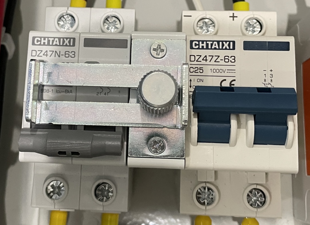
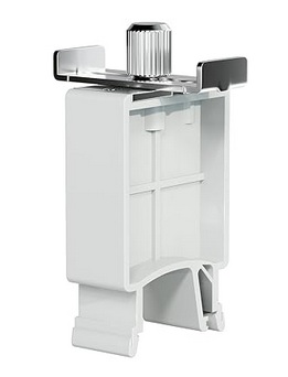
Problem:Mollum MCBs are not compatible with the interlock I purchased. Mollum breakers have the flip lever in the vertical middle of the unit. The interlock won’t slide with that configuration. So I purchased two Chtaixi MCBs after doing a bit of research (i.e. opening my eyes); its flip lever is located towards the bottom of the unit.
I Slid everything onto a DIN rail and it worked just as advertised. So let me show you how it looks in my control box build…
AC power…
DC power…
But, here is a cool feature that I just stumbled upon…Yup, when you want to lock out all incoming power from the genset or the PV array it turns into a “lock out”. Yeah, yeah…I know there is no place for a true padlock or even a tag to prevent sliding the interlock into operational capability. But, for me it is just a cool feature for added safety…not ultimate safety.
So, for a total of $48 I have the circuit breakers I need to disconnect power and protect the wire AND I have a device to safely and easily switch between power sources. Not a bad deal in my book.
And yes, you can use two AC breakers or two DC breakers for switch between power sources.
Okay, I’ve written a whole lot about our solar well and lightening problems; some here, some on a DIY solar website/forum. Bottom line…twice in 4 years we were hit with lightening transient voltage that blew up our control module for the solar powered well. Yeah, $600 for the first one $500 for the second control module. Simply put…unacceptable!
Yes, I installed all the appropriate grounding and surge devices but it turns out that it was the 700’ of signal wire between the water storage tanks and the wellhead that was acting like a giant antenna absorbing very small amounts of voltage (in the ground, from lightening) and sending it into the control module’s computer circuit board. Zap!
AND!!!! Along the way I found out that I didn’t need the control module to begin with!! Yup, that really ticked me off…$1,100 down the drain. So much for retailers selling customers what they need vs higher profit.
The “fix” turned out to be 2-stages; 1) get rid of the signal wire problem, 2) replace the control module including the very sensitive electronic circuit board with something more stable and safer. This review/article will be only about the signal wire issue.
I first tried to figure out how to protect the signal wire from the transient voltage. Long story…very long story…made short, I couldn’t do it in a manner that I felt was safe, reliable, and realistic. Plan B turned out to be simple…eliminate the signal wire altogether. And that turned out to be a wireless float switch system.
The float switch itself is a simple device that monitors the water level in the storage tank. When the water level drops it sends a signal to the well pump to turn on. When the tank is filled it sends a signal to the well pump to turn off. My problem was the 700’ of buried signal wire between tanks and well. A wireless system is just that…wireless…no wire buried in the ground to pick-up the transient voltage.
The signal is transmitted via a radio signal between a transmitter and a receiver. Everything else pretty much operates the same. Problem solved…installed it last week.
Summary –
Let’s make this easy for you. I will give you the bottom line right here and then you can read the rest if you want to…or if you need some reading material to fall asleep by.
After weeks of research and searching there was only one real option: RPS Solar Pumps’ Wireless Water Tank Sensor for Remote Pump Shutoff, the 24-hour version. Price $729 (on sale), about $800 all in with shipping and tax.
So here is the bottom, bottom line…It Works!
Unpacking & Problem –
You know, after getting sold the wrong pump by a retailer that didn’t really know what they were doing, and getting sold a control module that was 100% not needed…and then buying another control module that was 100% not needed I was very skeptical about the actual ability of this unit to do what it was advertised to do…and the price it was being sold for…and the ease of installation that the company was touting. I think you can understand that.
So the box arrives in decent time and apparently undamaged. I set-up for a video to show the unboxing as the first step in a longer video covering the install. “Action!” The box was packed well with plenty of protection around each solar panel and the attached transmitter/receiver units. Out comes the transmitter unit…nice. Next comes the receiver unit…nice. Ahhhhhh…that’s it…nothing else in the box. First thought that ran through my head…here we go…scammed again!
I double checked what was supposed to be in the box vs what was actually in the box. I was missing the float sensor, the antennas, the hardware, etc. More defeatist thoughts start rolling around in my head.
I checked to make sure I saved the video, pulled up the company website, and called customer support. Now this is where it could have been the end of the last of my faith in humanity. Thankfully I couldn’t have been more wrong. The CS rep was incredibly friendly and helpful. She listened and verified the missing equipment. She said she would get an order placed immediately for the missing parts. Then the other shoe dropped…”Do you have any pictures of what was in the box?”
Yup, first thought…they want verification that stuff was actually missing, thinking I was scamming them. But, thankfully, “Mam I took a video from the time I set the unopened box down on the deck through pulling out each piece that was there and then showing the empty box.” I guess that sealed the deal…order placed.
So on with the results of the unpacking…
Issue #1 – Safety : Exposed terminals on both batteries. Yeah, not a good thing. On both solar panels there was an attached battery. The battery had both the positive and negative terminals fully and completely exposed. Meaning…had a piece of metal touched both terminals it would cause a dead short in the battery…and that cold cause a fire. Very, very bad thing when shipping. All rechargeable batteries come with terminal protection when shipped. Someone at the RPS plant didn’t put the terminal protectors back on after assembly. And, the folks in the shipping department missed it as well. Not a good thing at all.
Issue #1.5 – Incompetence : Yeah, kinda harsh but factual. The order should never have left the warehouse without all the parts in the box. It is not hard to ensure all the parts are there in the box…not hard at all. But, RPS does get a compliment for their customer service and quick response to get the missing parts to me.
Received Missing Parts –
About 4-days later the missing parts showed up. Yes, I was skeptical all over again. Video rolling, box opened, all missing parts were no longer missing…all was good. Too bad they weren’t in the original box in the original shipment. The shipping department seems to have a bit of a problem. Solution: Have a pre-printed list for each different unit, the shipping guy goes down the list, the part goes in the box, it gets checked off the list, when complete, take a picture of the signed-off list, put the original list in the box, seal & ship. Problem solved.
Installation –
The installation was straight up and pretty simple. However, the installation video put out by the company is completely unrealistic in terms of time it takes to do the installation. Plan on 20 – 30 minutes per each unit, potentially more depending on your situation.
Issue #2 – Installation : The battery is located poorly. The battery adds weight in the wrong place, it is unbalanced. The battery should be closer to the base of the mounting bracket lowering its center of balance and gravity.
Issue #3 – Installation : The battery is located poorly #2. The battery is located too closely to the plastic box containing the circuit board. It makes it difficult for a person with large hands to get the antenna screwed in. Locating the battery closer to the mounting base would give more room to attach the antenna.
Issue #4 – Installation : The battery is semi-permanently attached to the mounting bracket. Trying to fix issues #3 & #4 I attempted to move the battery. Ah, no. It appears there is a large zip-tie holding the battery to the mounting bracket making it simple…slid the battery closer to the base of the mounting bracket…two problems solved. It did dawn on me that it seemed pretty lame to have the battery held on by nothing more than a zip-tie. When the battery wouldn’t slid down I noticed a double-sided foam piece of tape between the battery and the mounting bracket frame. No moving it. So, it is nice to have a little better mounting system for the battery…too bad the battery is located in a poor location and can’t be moved without major effort.
Issue #5 – Installation : There is a signal wire “pig tail” on both the transmitter and receiver units. RPS also includes a splice kit to attach the float switch signal wire to the transmitter unit and a signal wire between the receiver unit and the well pump. Why? Any splice is a potential point of failure of the system. Also, adds considerable time to the installation process. I simply opened the circuit board box, removed the pigtail wire, and then place the signal wire directly into the connection ports on the circuit board. Poof! Problem/issue solved…no more potential source of failure and time saved.
Issue #6 – Battery : Yeah, this is a fairly minor issue, but one that should not exist. Attaching the wire terminals to the battery “blade” style terminals wasn’t any fun. The first couple of attempts by hand were unsuccessful. And the battery being so close to the circuit board box didn’t help any. I finally had to use my pocket knife, separate the wire terminals a little bit, then use needle nose pliers to get a solid connection on the battery. Seems a bit unneeded and easily addressed at the factory. And, to make matters worse, the battery terminals and wire connections/terminals are open to the weather.
Overall –
Pros –
The float switch is not a mechanical float switch at all, it is a sensor. That fact makes it much more useful and functional…and I am thinking it will also last longer.
Solar panel appears to be of good quality and plenty large enough to do the job.
Battery appears to be of more than sufficient capacity to do its job.
The plastic box holding the circuit board is top notch and appears to be plenty weather proof.
The circuit board itself looks to be quality and well built.
There are 3 status lights in each unit. “Tank Full”, “Power”, and “Com”. The last one shows the unit is transmitting or receiving a signal to ill the tank.
The angle of the mounting bracket places the solar panel at a good compromise angle for winter or summer sun.
The mounting bracket itself is stout enough to do the job pretty dang well. The base holes are sufficiently large enough to do the job accommodating lag screws/bolts.
The antenna appears to do the job. Good thing is, if the antenna is too short, the circuit board box has a universal antenna connection…simply buy a better/longer antenna and connect it if needed.
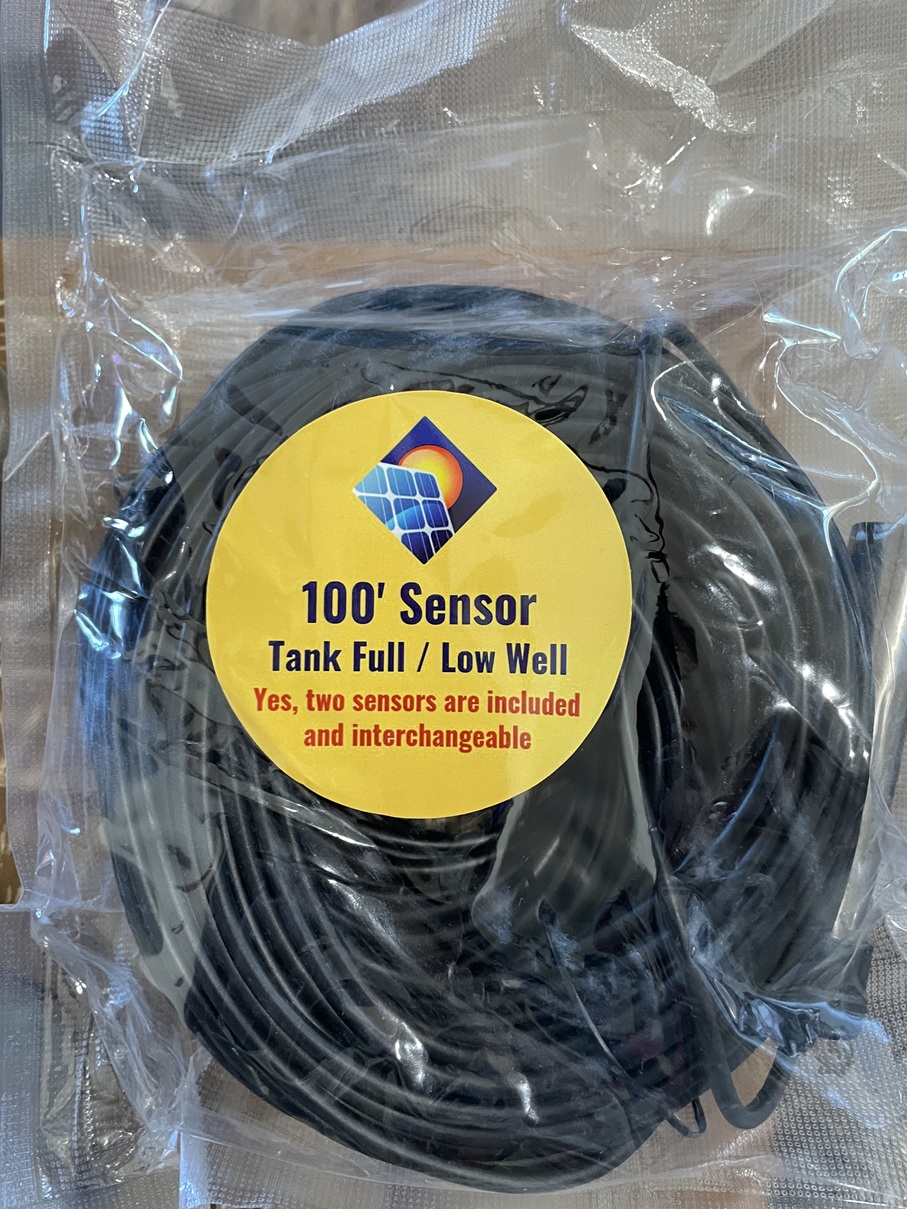
The signal wire on the tank float probe/switch is long…and I mean long. Supposedly 100′, but I didn’t measure it. Great to have so much wire to work with.
Overall, it was easy to get up and running within a reasonable amount of time.
2-year warranty and lifetime support.
Cons –
The wires connecting the circuit board box to the battery are really, really lame. While they are of sufficient size for volts/amps, their quality appears to be used on an interior space, not sufficient quality to be exposed to weather. It would have been very simple to use a weather rated wire.
The terminals on the wires that connect to the battery are even more lame than the wires themselves. The wires, while crimped, are not sealed against weather, dust, etc. A simple solution would be to use a heat-shrink terminal. Or, use a short piece of heat shrink after crimping the terminal.
The terminal on the battery and the terminal connections on the wire are completely exposed to the weather. Any weather can easily infiltrate the connection…potential point of failure.
The magnetic base on the antenna sucks. Yeah, meaning the magnet used is super weak. I mounted the antenna base on a 1-1/4” wide piece of steel…we’ll see how long it lasts once the windy season starts.
The included screws for the mounting bracket base appear to be adequate for mounting on metal. But, if mounting it on a the top of a post, such as a 4”x4”, those screws are wholly/totally inadequate.
Last but not least…mislabeled or missing part…again? So here is a picture of the water level sensor. Read the label…again. “Yes, two sensors are included and interchangeable.” Yeah, I unrolled the 100′ of wire and saw the sensor, the silver probe. So where is the other “sensor”? Notice the other wording…”Tank Full / Low Well” Ah, how do they know that my well has low water level?
click to enlarge
The two sensors are located in the silver probe; 1 sensor is “tank full“, the other sensor is “tank fill“. There are not two separate sensor unit, they are both located in the probe.
“Low Well“??? How in the heck could they know my well is low on water when the sensor is located in the storage tank!?! So a bad case of mislabeling. A bit weird if you ask me.
Kinda Weird –
So I bought the unit on rpssolarpumps.com. If you read everything on their website it sounds as if they make, or at least assemble, the unit themselves. Ah, no. When the unit showed up the instruction manual was from “Back 40 Solar”. And the overall instruction manual left a lot to desired.
The unit is actually made by a company called Back 40 Solar (https://www.back40-solar.com/). So RPS is just the distributor not the manufacturer. But don’t try to buy direct from Back 40 Solar…they apparently only sell through their distributors.
And “rpssolarpumps” is actually Rural Power Systems (ruralpowersystems.com). So there appears to be a bit of an identity crisis going on here. But, I am not particularly worried…the unit worked even if RPS was a little dysfunctional fulfilling the purchase.
Yeah, I have no idea why I thought the Back 40 Solar vs RPS issue was “weird”. I think it just caught me by surprise that RPS was selling a Back 40 product. But hey, why not. Now I just have to figure out how to get this review to Back 40. Yeah, another interesting little tidbit…Try to find a way to contact Back 40 Solar. On their website I couldn’t find any email address, no phone number, no physical address, no mailing address, no contact form, nothing. Okay, there was a form you could fill out if you wanted to become a dealer. No, I don’t want to become a dealer. I did find an email address embedded in the html code of one of the pages so I will send them this review at that email address.
Anyone else find this weird or is just me? It appears that Back 40 Solar wants to stay hidden for some reason; they want no contact with actual customers. I wonder why. The distributor, RPS, does seem to be responsive so maybe it is no big deal…we’ll see.
Recap –
As I stated at the beginning…it works. Yup, that was the main goal…it needed to work which in turn eliminates 700’ of signal wire. And that hopefully eliminates the stray transient voltage that was frying my controllers. And it appears it will do just that…mission accomplished.
Here is a big whine on my part…price. Yeah, this thing ain’t cheap…retail is $949…and that is some serious coin. In October they were running a sale…$729 until 10/30. I bit the bullet and bought it a couple days before the end of the sale. Yeah, well, a week later I went back to the website page to get some info and it was on sale once again for $729 until11/30. Gee…perpetual sale. Just kinda throws up a red flag for me. Yeah, not sure why…just does.
Did I mention that the unit worked? Yup, sure does…mission accomplished…I’m happy…so far.
Sad part is, if they increased the quality of materials and construction just a bit, it would be a great unit vs a good unit. The total cost of the improvements would probably be less than $5…at most. And then add in the shipping department fix…BINGO! A great product and a better purchase experience.
I won’t, or at least shouldn’t, complain about the price. If I figured the cost of 700’ of shielded signal wire plus trenching cost/time the $729 would probably be right in the ballpark of a good deal. Throw in the cost of two burned up controllers and even the $949 price would be reasonable…staggering, but reasonable all things considered.
Now for a reality check…whether $729, but especially for $949, it is not acceptable to have half the parts missing. It just ain’t right. But, they did step up and make it right…but, there should not have been such an egregious/simple mistake to begin with. But, well done on fixing the missing parts issue. And the RPS customer support person was amazing!
Once again…bottom line…It works! It spanned the 700’ distance between the storage tanks (float switch) and the wellhead (pump controller) with no issues. Now here is the real test…Would I buy it again?Absolutely!! Another test…would I pay the $949 full price vs the sale price? Yeah, probably, I would begrudgingly buy it…but clearly I would whine a lot more about it. But it works!! And that is what really, truly matters.
Side Note: I am wondering if I should start videoing all unpacking of purchases made online. You know, anything expensive to document exactly what is going on…damage, missing, etc.
My experience with an MCB Interlock device has been a total success so far.
I needed to build a control box for my solar well. My solar well pump can directly accept AC or DC power. Part of the box build included an AC inlet for my genset and the incoming DC power from the PV array. I needed to make it easy to switch between power sources quickly and safely. And ensure that power could not come from both sources at once. Although highly unlikely that would ever be attempted, I wanted to ensure it as an impossibility. Hence, the “interlock” concept.
I first heard about their existence here on the forum, I don’t remember which thread. I purchased an interlock device off Amazon along with two Mollum MCBs; 20aAC and 25aDC. They arrived, and it didn’t work.
Problem: Mollum MCBs are not compatible with the interlock I purchased. Mollum breakers have the flip lever in the vertical middle of the unit. The interlock won’t slide with that configuration. So I purchased two Chtaixi MCBs after doing a bit of research (i.e. opening my eyes); its flip lever is located towards the bottom of the unit.
I Slid everything onto a DIN rail and it worked just as advertised.
So let me show you how it looks in my control box build…
AC power…
DC power…
But, here is a cool feature that I just stumbled upon…
Yup, when you want to lock out all incoming power from the genset or the PV array it turns into a “lock out”. Yeah, yeah…I know there is no place for a true padlock or even a tag to prevent sliding the interlock into operational capability. But, for me it is just a cool feature for added safety…not ultimate safety.
So, for a total of $48 I have the circuit breakers I need to disconnect power and protect the wire AND I have a device to safely and easily switch between power sources. Not a bad deal in my book.
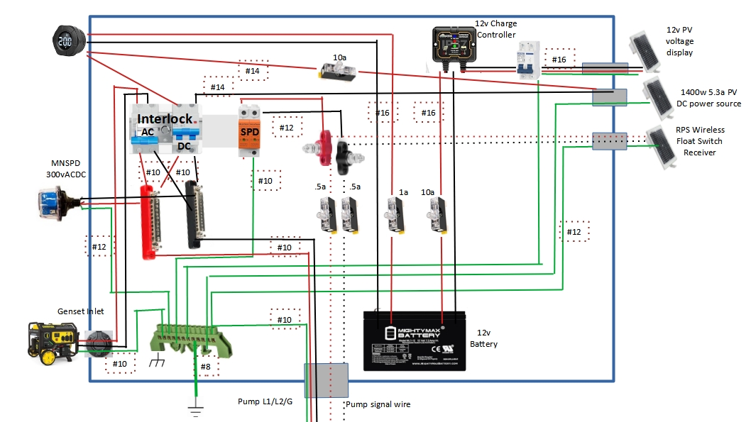
I am including the well box schematic below. Anyone’s input would be greatly appreciated…ANY! Yup, that means questions, concerns, issues, warnings, safety problems…and even compliment 😉
I am actually in the process of building the box right now…hurry, feedback needed.
I really want to write a little series of articles that, when combined, show a couple points that bug the crap out of me. But…I’m really not sure on where to start. Let me touch on the general points first, then maybe a starting point will manifest.
Points to Ponder –
You gotta know a bunch of stuff to go off-grid and/or work a homestead…or you need to be willing and able to learn.
Businesses are usually stupid…or don’t really care that much about their customers.
The simplest solution is usually the best/right solution.
There are some really great products out there…but they are usually really well hidden.
Don’t ever trust salesmen.
Mother nature rules…and can trash mankind whenever she wants.
Trying to be self-sufficient is a pain in the a$$…and expen$sive.
Yeah, you kinda get an idea of just how frustrated I might be?
Let me start all the way back at the beginning…
We bought our place 10 years ago…and I can’t express how grateful we are for God bringing us here. Fortunately for us it already had a well on it. Yup, that is an expensive necessity around these parts. Once we closed on the place I contacted a local well company to pull the pump and test the well…and refurb it if needed. We got lucky…the well was in great shape and needed no work on it.
There was no power at the well to run the pump and the pump, although working fine, was 30 years old and 220vAC. I went to a then local well supply house, outlined my situation, they recommended a new pump set-up, and we bought it. I installed it myself a couple years later and all was fine…till we needed to irrigate the garden, yard, and small orchard.
So we found out…not enough storage, not enough pump flow, WAY inconvenient to use a generator to run the pump…just not the right way to supply our water needs. So again, I contacted a now local solar business guy that I was friends with for advice. “Solar pump!!!” was his suggestion and he supplied me a quote. More money than we wanted to spend…but it “would cure our problems.”
I installed it myself and all was good…kinda. We weren’t getting the flow we needed (amount of water pumped out of the well) and we could only run the well during the day when the sun was shinning. And then disaster struck…a thunderstorm. “ZAP!!” A nearby lightening strike took out the well control module. It was under warranty but we had to send it in. Ahhhhhh…it would take at least a week, probably two, to get it back. Solution from the company…”buy a back-up controller”. Another $500 down the drain…but we kept on pumping.
Turns out that when the nearby lightening strike hit there was transient voltage that spread out towards our place and was absorbed by the signal wire between the well control module and the storage tank’s float switch…700’ in between. The hit wasn’t bad enough to show any damage on the controller’s circuit board…but enough voltage to kill the display board which in-turn killed the operational ability of the module.
Transient voltage refers to quick and very temporary spikes in electrical voltage,
typically lasting only a few milliseconds. The spikes can be caused by near-by lightning strikes,
switching operations, or electrical faults. And they can potentially damage sensitive electronic
equipment such as circuit boards.

Float switch is a unit that floats in the water tank and tells the well pump
when to turn on and send water to the tank and when to turn the well pump off
so the tank doesn’t overflow.
Basically, and on/off switch controlled by the water level.
So a little time goes on and we expanded the orchard and garden and yard…now way too little water to irrigate. So, another storage tank. Fortunately a decent and reputable local company gave us a deal, installed the tank myself, back in business with plenty of water to irrigate.
Another thunderstorm…we noticed tanks overflowing sometimes. Three months of troubleshooting later…problems with the new well control module. Yeah, from you know what. Fixed it ourselves…back in business. Well, kinda. (no pun intended). We still had a problem getting enough water to irrigate the orchard, garden, berry patches, grass, and the new pine trees. Began a slow process to think about a better solution.
Another thunderstorm with a near-by lightening strike…a dead well control module…the new module now dead. No problem, I had a back-up on the shelf (the original control module), installed it, contacted the company, they said send in the dead unit. Turns out the unit was dead as a door nail…completely bricked. $500 down the drain. And the control module now on the well was the “repaired” unit from the first lightening strike and was/is limping along on borrowed time.
Fed up with the situation I decided I better get thoroughly educated on all aspects of the solar well set-ups and what exactly was causing our problems. Two months later I finally had a handle on it. The problems:
The well control modules were getting zapped by transient voltage from nearby lightening strikes.
That transient voltage was coming in through the 700’ of buried signal wire between the storage tanks’ float switch and the well. Basically the wire was acting as an antenna collecting the voltage and shooting it into the electronic circuit board inside the well control module.
No off-the-shelf solution was available that wasn’t cost prohibitive. Meaning…at a least couple thousand dollars to install an applicable and reliable solution.
But…here is the ugly part(s)…
The original local dealer sold us a pump that didn’t meet our water supply needs when he could have if he had simply listened to us when we talked about the well depth, water needs, etc.
AND…the same dealer sold us that control module that was completely unneeded. There was a much less expensive and far simpler way to control the well pump.
When we worked directly with the pump manufacturer, who sold us the 2nd control module directly, they sold it when it was completely unneeded. Again, there was a much less expensive and far simpler way to control the well pump.
Neither the local dealer or the manufacturer had any solution for our situation.
But is gets worse. I accepted the situation for what is was and knew I had to figure out a solution myself…so the research began. I found a wireless float switch that would eliminate the 700’ of signal wire that was collecting the lightening transient voltage…$800. But there still a problem with the well control module and it was going to breakdown at some point. Along with that bad news was some really good news…the pump itself was very high quality and had really great options. However, the control module we had/have couldn’t access those truly useful options.
Yes, I ordered the wireless float switch. Wanna hear some irony?
The box with the new equipment arrived, a week after I made the purchase.
I made time to start work installing it on the existing module for a test run.
I set-up my camera to video the unboxing to post later.
I pulled out the first two pieces of equipment...ah, that was all there was.
The antennas, the tank probe, and some hardware were all missing!

Fortunately, I had the video.
I called the company, explained the situation, told them about the video,
and the really great customer service person created an order for the missing parts.
 They shipped the next morning.
A very awesome and needed option for the pump was…for basic operation the pump could run off solar panels or a generator very easily with nothing special needing to be done. The current well control module had no ability to implement that option. But, the well control module had options that meant absolutely nothing to me and were completely unneeded. After weeks of research, and a dozen emails back and forth to the “manufacturer” (turns out they were a distributor) I now understood how the pump worked, options for operation, and basically how it functioned overall. Interestingly enough…the pump itself was not “made” by the manufacturer, it actually was made in Italy and then private labeled by this company in Arizona.
The part that ticked me off the most…I could have had more than twice the pump/flow rate with the same type and quality of pump if the local guy had known what he was doing. He sold us a pump for a 750’ deep well vs. a pump for a 220’ well. Another model of that pump provides more than twice the flow rate for the same money for a 300’ well. Nothing I can do about that now…just move on.
So here is what I needed/wanted to control my well:
Earlier in the day pumping and more water in the storage tanks during the summer months.
A safe and reliable way to control the pump.
An easy way to be able to run the well from the solar panels or a generator.
A reasonable and realistic way to protect a control module and the well pump from lightening strikes.
Obviously there is no way to protect from a direct lightening strike, at least one that is affordable, but I could expect protection from the transient voltage issues that was burning out the existing control modules.
PROBLEM!!!! I couldn’t find anything to fit those requirements…nothing!
Come on…was I being unreasonable? I can’t be the first guy to run into this. And, it isn’t complicated. One limiting factor was my existing pump…I was stuck with it and its limiting flow rate. To replace it was simply too expensive. So I had to figure this out on my own. And I did!
I will write another article on what I am building for a solution…but, that isn’t the point of this article. Here I just want to point out the back-story and the lessons learned. I will do a “Part #2” that will be the lessons learned. Part #3 will be the overall solution to the problems/issues/challenges.
If you remember I upgraded my entire battery bank in the spring (2025) and increased battery storage from 32kWh to 41kWh (630ah – 800ah) < click here >. I also went with a “closed loop” battery bank connected to my Victron CCGX. The Midnite MNPowerFlo5 batteries now control the charging vs the charge controller “smart network” and GX device. Other than me tinkering with the DVCC settings (which I learned my lesson not to) the system has been up and running with no real problems of any kind. Well, almost…
I did the upgrade in March…which is clear and cool weather with bright, clear, sunny, blue skies. Just about perfect conditions for maximum PV production. And then July came around. Here in AZ the monsoon season usually starts in July, along with cloudy skies, sometimes for 2 – 4 days in a row. So out came the generator to occasionally top off the batteries and/or keep the lights on. And that is also the time period when I started messing with DVCC settings. Yeah, bad combination.
A number of Victron experts on this forum helped straighten me out, educate me, and turn all the DVCC settings back to the defaults. Thanks guys!!
But, I still had a solar production problem. Yeah, I didn’t do a very good job of calculating the peak solar/sun times for each month…July – September can be the cloudy season, and I didn’t really account for that very well. I often couldn’t get the batteries up to a full SOC, sometimes not even close. Hence, the genset usage.
I am 100% off-grid and wanted the battery storage to carry me almost a week on my household “minimum load”; I achieved that with the 41kWh of batteries. But sufficient energy storage without sufficient energy production kinda leaves you us in the dark…no pun intended.
My system has “evolved” over the last 6 years. Finally settling on almost entirely Victron…smurf through and through! My PVs…well, a mess. I started on a shoestring budget and have pinched pennies since then when it came to PVs. Some would, rightfully so, criticize that…but that is just how it happened.
I had/have 3 arrays;
800w (8x100w HQST 18v/5.5a) mounted on my utility room roof facing south-south-east (165degrees), first array built,
2235w (6x250w Canadian Solar 30v/8.3a) + (3x245w Canadian Solar 30v/8a) ground mount facing south-south-west (210degrees), array built a year after the first,
2235w (6x250w Canadian Solar 30v/8.3a) + (3x245w Canadian Solar 30v/8a) ground mount facing south (180degrees), array built a year after the 2nd array.
Arrays #1 & #2 combined into a Victron 150/70. Array #3 into a separate Victron 150/70.
Arrays #2 & #3 evolved; they each started with the 6xCS 250s and then I added the 245s (3 each) last year. Yeah, not the best method, but close enough for me at the time.
Arrays #2 & #3 were all used panels, but I tested them and they were producing at 95% rated capacity…and I got a killer deal on them at the time.
Array #1 Upgrade –
I knew I had to increase production but the roof of the utility room limited me on the size of panels I could put up there. And my wife was severely limiting the upgrade budget as well. My solar business buddy gave me some used 175w Solar World panels (37.5v/5a) (tested out at 97%), couldn’t turn them down and they were a good fit for the utility room roof. I was able to install 6 of those panels for a production increase of 31% (2S3P) over the old panels.
Additionally, combining Array #1 & #2 couldn’t be a good thing; 1) different panels, 2) different compass points. True south for our location is about 170 degrees; #1 was spot on, #2 was 20 degrees off. I am sure the MPPT had “issues” trying to workout the charging algorithm making it inefficient.
There wasn’t much I could do to increase production significantly at this point. But, I could remove the 6x250w CS panels and replace them with matching 6x245w CS panels. That gives me 9 matching 245w Canadian Solar (30v/8a) panels with no loss of production.
And since it will now be on its own Victron 150/70 MPPT Smart Solar Charger I should see more efficient, more production, out of the panels. Additionally, I will be painting the frame with all the panels removed and cleaning up some wiring.
Array #3 planned upgrade –
This array was the one place where I could increase production. So I will be removing all the panels, making frame modifications for another 6 panels, frame painting, wiring improvements, and panel reinstalling. I will then have a total of 15 x 250w Canadian Solar (30v/8.3a) panels on this array (3S5P).
And once again, since all panels will now be matching 250s I should see an efficiency increase there. And adding 6 more panels will increase the array by 1500w.
Projected Overall System Production Increase –
Additional 1750w in additional panels (plus another 1500w this winter)
Efficiency increase with the added 100/20 MPPT on Array #1,
Efficiency increase with matching panels on Array #2 & #3.
Current Project Status –
All of the work is done on Array #1, including the addition of the 100/20 MPPT.
Array #2 (phase 1) starts on Monday. Phase 2 will be this winter.
Array #3 starts the following week.
Watching the production side the last couple of days…yup, seeing more production with simply upgrading Array #1 so far.
Something New –
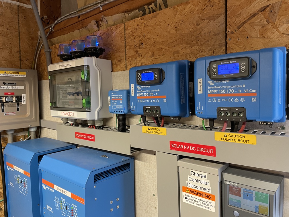
I was not happy with the array disconnect switches in the utility room. They just weren’t right for the job. So I came up with an “elegant” solution. Okay, maybe not elegant, but pretty cool IMO. I built a PV disconnect box. I integrated an appropriate sized circuit breaker for each array as the disconnects along with the SPDs.
Here’s the old set-up… Here is the new set-up… So each array has an exterior combiner box with fuses on each string, a circuit breaker for the array, and a Chinese SPD for the array. Then inside the utility room there is a circuit breaker (acting as a disconnect switch) and a Midnite Solar SPD. I like it!
One last thought…I looked and looked at Array #2 trying to figure out how to add substantial production capability to it. Location and spacing with the garden just wouldn’t let that happen. But I have another matching 6x245w CS panels…I didn’t want them to go to waste. I figured out that about 20’ away I can add another ground mount frame with the 6 panels and run them (3S2P) to the combiner box on Array #2. That will add another 1500w to the system sometime this winter.
Old production – 5.2kw
New Production – 8.5kw (when I am all done this winter with Array #2 – Phase 2)
So this is how I am upgrading the production side of the system…this time…and this winter. To me to just seems as if it never ends…it’s never enough. Oh well, the joys of solar, living off-grid…and evolution.
Twenty-two months ago I added a new 230ah 48v Trophy battery to our solar system. That coincided with a major upgrade to the entire solar system we have here at the glamstead. The system seriously changed our lifestyle in several ways; 1) air conditioning all night if needed, 2) bathroom electric baseboard heat 24/7 in the winter, 3) and double the AC power along with 240v capability. The system purred along flawlessly…until about 5 months ago.
Sometime in September (last year) I just happened to be in the utility room and I noticed that all batteries were charging, but the two Elite batteries (205ah 48v) were not displaying the same number of lights on the State of Charge (SOC) indicator. One was at 83% and the other was at 67% SOC but both were charging. I thought it was nothing more than a balancing issue so I basically ignored it. Ooooppppssssss…
A week later I was again in the utility room to get a tool on a cloudy day and I noticed that the lights were once again doing the same thing but not charging…it was 100% overcast. Now it got my attention. Fast forward 5 months…problem with one of our Elite batteries. From my best guess it is now at about 70 – 75% total capacity of the other Elite battery. Meaning it is now a 145 – 150ah battery. Not good, but not life endangering either. Obviously the battery has one or more weak “cells” in my way of thinking, the other cells are still doing their job.
Let me do a quick recap…I have 3 batteries in my solar system; a single 2-year old Trophy battery that is 230ah, and 2 Elite batteries that are 205ah each, totaling 640ah or 37.7kwh. Decent sized battery bank for an off-grid home. The two Elite batteries were bought at different times, 1 in early 2021, the other in late 2021. The Trophy battery was added in December 2022. All batteries match charging parameters (+/-.1volts).
I initially thought the batteries would eventually balance, match similar SOC, and maintain that for the most part. I was wrong. Each battery acts independent in charging and discharging…which actually turned out to be a blessing. The Elites generally discharge slightly faster than the Trophy and generally lag when charging. But no problems overall with maintaining a nice amount of power in the bank. Well, until I noticed the one Elite having an issue.
A visit to the shop where I bought them was warranted…for a warranty claim. (yes, pun intended) Ah, problem…the commie company in China that made the batteries was no longer around and not available to stand behind the warranty. That’s what I get for “bargain shopping” critical components. Yes, I did know what I was getting into at the time…money was an issue.
So here is where I’m at…battery bank is now at about 590ah vs 640ah. Let’s call it an 8% loss of power storage…maybe 10%. And on top of that…a weak battery with no idea for sure how long it will last. The good thing is that each battery is acting independently and doesn’t “draw-down” power from the other batteries to maintain the weak one. I guess it is a combination of the batteries’ BMS controllers and the design of the LifePo4 chemistry. But, I am still left with a somewhat bogus battery.
The owner of the shop where I bought it is also a very good friend of mine and felt terrible about the problem…but I was not the only person in the same boat…but he couldn’t stand 100% behind the warranty without the manufacturer supporting him. Unfortunate, but understandable. Given that he is a trustworthy person we came to a deal…he would do a “cost only” sale…and would do a trade for the amount due for something I had that he wanted and I could easily live without. Done! But here is where it gets interesting…
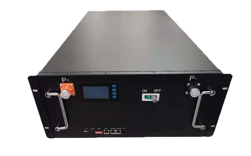
200Ah batteries are not cheap as of yet, although 100ah batteries have come down dramatically…now $800 – $1,000 all over the place. I will be the proud recipient of two of the new MidNite MNPowerflo5 Lithium Iron Phosphate server rack battery (100ah, 51.2v, 5.1kwh). The charge parameters are close enough to my existing batteries that there will be no issues. But WAIT you say! These are 100ah batteries not 200ah batteries…they won’t work!!! Ah, they will.
You see I will place the 2 new batteries together and parallel connect them together, then connect them to my Victron PowerIn bussbar unit. My system will then see the 2 new batteries as a single 200ah battery. And, each batteries BMS will control the batteries as needed during charge/discharge operations.
Here’s what the new battery bank will look like…
So a logical question would be…So these two new batteries replace the one existing weak battery? Nope!
The “weak” battery is still fully functional/operational at this point…just not maintaining its full capacity. So I will keep the weak battery in the bank and simply add the two new ones. Yup, that takes me from about approximately 590ah (30kwh) to 770ah (39kwh). Not bad, eh? And yes, I will keep a close eye on the weak battery and remove it from the bank if I notice it harming overall system operations.
Moral of the story…sometimes a problem turns into a blessing.
Also…I want to add into this conversation a point that I cannot stress enough. If you are going to have solar, especially if off-grid, it is essential to have some knowledge about how solar works…including the equipment specs and the general theories of each process step. Why? Can you imagine if a retail guy had installed the system, and I had the same problem, what would/could have been the outcome?
I can tell you this…based on people I know who were in trouble situations (i.e. not enough panels, not enough batteries, etc.) most solar companies would try and sell you a whole new system, or at least part of one) and make it sound like the only viable option. Why? Because an unknowledgeable solar system owner would have no idea that the real problem was only a single weak battery…an $1,800 fix vs laying out 10’s of thousands of dollars for stuff not needed.
Yeah, I can’t help myself…I will post about the install/upgrade and include pictures. And FYI…I got my hands on 6 more compatible solar panels so you know what that means…a new array for the system in the near future!!!
There are important and serious things going on in the world today…Liberty Safe Scandal is not one of them.
It has been known for decades that Liberty Safe has been cooperating with law enforcement, specifically the ATF and the FBI. And folks, not just with the digital keypad safes. Combination safes have an identifying number on them as well. LEOs call Liberty and Liberty would freely and willingly give the LEO the combination.
So it’s not a matter that Liberty licks the boots of LEOs…its that people didn’t take the time to learn of it.
Or, a better question…why would you have anything in your safe that you didn’t want the FBI to know about? Really, if the FBI wanted into your safe…they would get it, period. So why keep stuff in the safe if you didn’t want it found? Court order or blow torch…they getting in!
Now, maybe the right question would be…How did the ATF and FBI convince Liberty Safes to so freely and willingly cooperate in violating the 4th Amendment to destroy the 2nd Amendment?
Maybe it has something to do with the owners of Liberty Safe…Monomoy Capital Partners. And who might they be and what are they all about?
One of the things that can get confusing, but is extremely important, is knowing what size of wire to use when working with DC circuits. And once you get the wire size figured out…then trying to figure out what size fuse should you use.
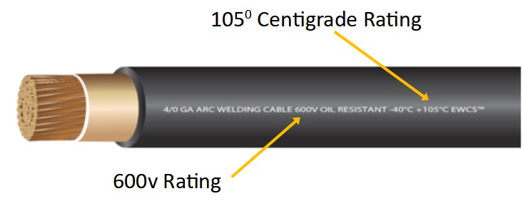
So I’ve included a wire sizing chart at the bottom of the page for you to download. And I will provide a couple of tips as well. Finally, I will provide a link to a great little sizing and fusing calculator that I think makes everything much easier when trying to calculate all of this. But first, some good information to know…Also, it is important to note that when dealing with DC currents in solar power systems (SPS) you need a high-quality wire with a good insulation rating; 105 degrees centigrade is commonly referred to as the standard. Voltage rating should be “600V”. Also, stranded wire is best when using wire in the DC side of SPSs…the more strands the better. But, a good measure would be as follows, with each strand being 30AWG wire…
Most wire wire/cable will come with rubber or rubber-based insulation. Silicone-based wire insulation is generally considered superior to rubber-based wire insulation for a number of reasons, one being a higher heat rating, up to 200 degrees centigrade. Silicone is the most fire-resistant of common insulation material, it is also highly resistant to extreme environments. Then we also see silicone as being more flexible and more compression resistant. And yes, silicone is more suitable for outdoor applications, but when running wire outdoors it’s always best placed inside a protective conduit.
Aluminum wire should not be used…period. Copper wire is the standard for DC applications due to its high electrical conductivity. However, there is even better wire than standard copper wire, tin-plated stranded copper wire. Tin-plated copper wire is noted for its longevity because of its anti-corrosion properties. And, studies show that this variety of copper wiring is able to withstand adverse weather conditions and end up lasting far longer than the standard copper wires. It’s also preferred in applications where the wire will be exposed to a high degree of humidity. And lastly, tin-plated copper wire has more electrical conductivity as compared to other varieties of copper wires. And yes, it is more expensive.
Here is a little tip for you…up-size wire recommendations one size. Yup, look up the recommended wire size…then go with one size larger. This gives you a measure of safety when deciding on your wiring. Better to have a wire/cable one size too large than one size too small. One size too small can result in more resistance and potentially melting the wire itself. And obviously, if you melt wire it is a bad thing, a very band thing…which could result in a fire.
And that brings me to another tidbit of information that should be, will be, important to you…protecting your wire from over-current. The reason you protect your wire from over-current to prevent melting wire/cable and the possibility of fire is plain and obvious. So you put a fuse in the circuit.
Quality equipment manufacturers (Tier 1 companies) will provide fusing and/or circuit breakers internally to the equipment to protect that equipment. It is the installer’s responsibility to protect the wire connecting the equipment with fuses and/or circuit breakers.
Looking at a fuse and its job is pretty simple…the job of the fuse is to melt its wire or plate element at a lower current (amperage) than the wire can handle. That breaks the circuit and stops the flow of electricity. If the fuse is rated for a higher current than the wire, then the wire become the fuse by failing before the fuse blows.
Here’s an example: 1AWG wire is rated to handle 150amps at a total circuit of under 15′ (up-sized one size). Now, if you wanted to protect that wire from failure and put a 200amp fuse in the circuit…the wire would theoretically fail at 150amps before the fuse “blew” (a.k.a. opened) at 200amps.
To avoid this problem in our example you would use a fuse of slightly less that 200amps…say 125 – 150amps. That way the fuse would do its job before the wire failed and caused a potentially serious problem.
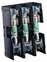
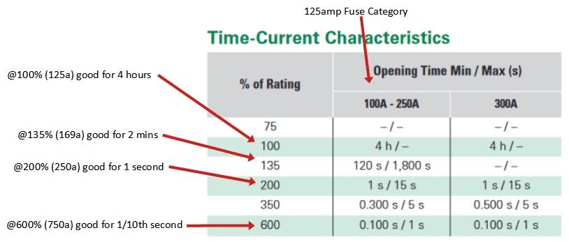
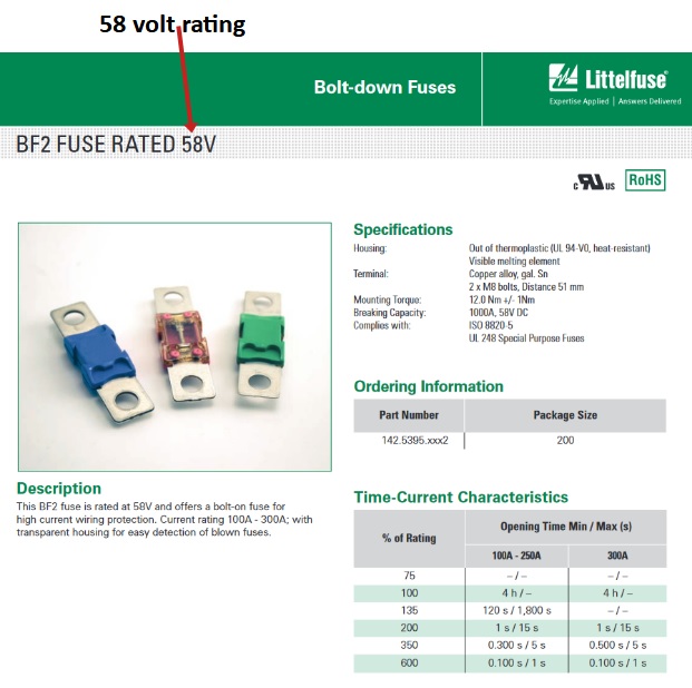
And here is another thing to consider when deciding on the correct fuse to use…its different ratings. So take a 125amp/58v BF-2 fuse from Littelfuse. It is rated at 125amps, yes? But does that mean it will blow as soon as the current hits 126amps? No. If you review the chart that accompanies the fuse you will see it will maintain integrity for different lengths of time at different currents (amps).
At 100% of rating, in this case 125amps, the fuse will maintain integrity for 4 hours. If the current rises to 135% of its rating (169amps) the fuse will still be good for approximately 2 minuets before it opens/blows. At 200% of its rating (250amps) it will open/blow at about the 1 second mark. And at 750amps it will open/blow at about 1/10th of a second. So before you decide on the right fuse looks closely at its ratings.
In our 1AWG, 200amp wire circuit at a full 200amps of current, the 125amp fuse would blow in 2 – 3 seconds
Also, notice the fuse description in the example, “125amp/58v”, that means it is rated for 125amps only up to 58volts. Meaning, if you try to employ it in a circuit above 58v it will not function correctly…as in fail.
What??? And why is it rated at 58v, sounds strange, eh? That fuse is designed for 48volt solar power systems. So why the larger than 48 voltage rating? Remember that solar power system voltages can run as high as 56 – 58 volts +/- coming out of the MPPT charge controller.
Now, let’s return to the wire insulation rating. Remember I mentioned that wire should have at least a rating of 105 degrees centigrade? That means 220 degrees Fahrenheit. That is above boiling temperature of water before it fails. Silicone insulation can handle almost 400 degrees Fahrenheit before failure. So you can see one of the obvious benefits to silicone wire insulation. Now, that being said…if you are building a circuit counting on silicone’s ability to handle almost double the temps vs rubber-based insulation…you are building the circuit in dangerous country. Consider redesigning the circuit more for safety.
And there is one really misunderstood aspect of deciding on wire/cable size…the distance or length of the actual wire run. Most folks will look at the circuit and say there is 5′ between the pieces of equipment and then use that to choose the wire/cable size. WRONG!! You use the total distance of the run…round trip. The circuit is the round trip of the current. So 5′ between equipment is a 10′ distance/length.
OK, so here is the long awaited chart with one note before the displaying it…when looking at the “circuit type” use “Critical” and “3% voltage drop” and when looking at the distance, the distance is the maximum run. So when you see 15′, that means up to 15′ round trip. Notice the “round trip”…that means the wire going to AND from the two devices.
( This is a very large graphic chart. Click to enlarge or you can download it as well. )
“Voltage drop”…don’t worry about it…just use “3%” when using the chart. But if you really want to know…voltage drop is the amount of voltage will be lost through “resistance” in the wire. Meaning the lower the quality of the wire, the more resistance, the more voltage drop, resulting in less energy being moved from one device to another. Yes, that is a bad thing, it’s a waste of energy. That is the reason to correctly size wire…to efficiently move current/power through the wire.
Now, let’s talk about the wire sizing and fusing calculator that is found on the “explorist.life” website. I like it…I like it a lot! You input the “amps”, the “voltage”, and the round trip length between the devices…then it shows you the recommended size of wire/cable to use to safely and efficiently carry that current. I like to reduce the “voltage drop” to 1.5% when using the calculator. That gives an extra margin of safety and efficiency.
There is also an option “Show Fuse Sizing Recommendations ” it gives you a great bunch of fuse information; 1)Minimum Fuse Size, 2) Recommended Fuse Size, 3) Max Wire Capacity, 4) Max Fuse Size. That is great, and critical, information to help guide you through making those design decisions. But again, I like to up-size the wire/cable one size just to be safe…and it allows for a little system expansion should the need arise.
And yes, https://www.explorist.life, run by Nate Yarbrough, has a lot of great information for you if you care to look around, including some very good videos.
TakeAways –
Use high quality, well insulated, stranded wire in DC circuits.
Up-size the wire by one size.
Use the right chart and/or calculator to determine the correct fuse size.
Ensure that the fuse rating(s) always are lower than the wire rating.
If you don’t understand all of this…then you shouldn’t be doing it yourself.
So I have been doing extensive research on off-grid solar systems because I will be upgrading our system after Thanksgiving. I am adding more solar panels, a 2nd charge controller, and a 2nd inverter. Along with that a general upgrade replacing some fuses and switches with circuit breakers, plus up-sizing some wiring. And to make sure I was/am on track I am seeking out information from reliable, expert, professional sources such as the manufacturers themselves, installation engineers, etc. Oh boy, I was surprised, disappointed, and a bit disgusted in what else I found.
Along the way I came across a whole bunch of folks, most of whom have YouTube channels, that are putting out some horrible, terrible, and potentially dangerous information. I mean some really, really bad content that on the surface sounds fine, but when compared to factual technical information is…well, pure junk. One of the problems I saw was mis/dis information about manufactures.
Let me start off by saying this…I’ve been building solar projects for over 10 years now. And, after my initial 24volt residential off-grid build here at the glamstead I realized I was working with 10-year old technology centered around lead-acid batteries. Seeing the problem rather quickly I started the first up-grade to 48v LifePo4 batteries, new inverter, etc. As I was doing the upgrade I asked the local solar dealer to ensure I had top-quality, Tier 1 equipment that I wouldn’t have to worry about. He provided Victron Energy equipment. I am so glad he did. But, back to the problem of mis/dis information about manufactures.
Part of my overall research was ensuring that Victron equipment was top-of-the-line stuff. During the research I found the real problems were far and few between. The performance problems came from under-powering the equipment itself…too small of a battery bank, too small of an inverter, too few solar panels, etc. So it was more of a system design problem than an equipment quality problem. There were two problems I found on the Internet that were serious…one inverter catching fire and one MPPT charge controller burning out. In both cases it was a wiring issue. The MPPT had a bad wire connection in the battery + wire connection inside the MPPT…installer fault. The inverter fire came from another bad wire connection inside the inverter with the battery + wire. Both times the wire wasn’t properly prepared or correctly connected to the equipment. Interesting to note…Victron did a warranty replacement on both. So the equipment was fine, the installers messed up.
Well, let’s wrap this up…a lot, most, much, of the solar information on the Internet, especially YouTube, is pure crap. It is misleading, poorly written, poorly produced, mostly DIYs, and overall just bad info. There are lots of sources out there with great information…but it can be had to sort that info from the junk info.
So Beware!
I am really concerned for folks who are doing a residential solar DIY project. This is especially true when someone is attempting a whole house, grid-tied, any system that is 48v, or any system with lithium batteries.
Why?
I don’t want to see anyone burn down their house, run afoul of their local utility company, get electrocuted with high-voltage / high-ampere system, or blow up or start a fire with a lithium battery.
So please go with only the best quality information sources, stay away from “garage experts”, and verify all information with manufactures before implementation. That is especially true with “hacks”, “shortcuts”, or “huge savings” promoting information….as well as any equipment engineered in China.

 My experience with an MCB Interlock device has been a total success so far.
 I Slid everything onto a DIN rail and it worked just as advertised. So let me show you how it looks in my control box build…
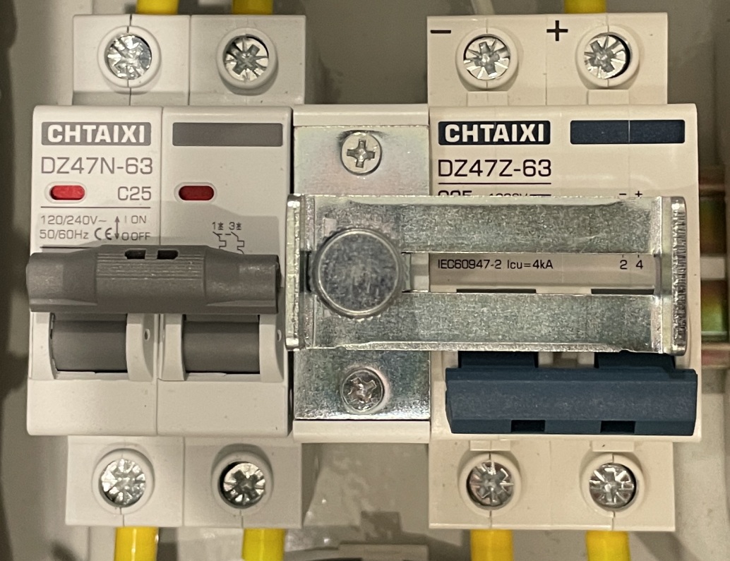 DC power…
 But, here is a cool feature that I just stumbled upon…
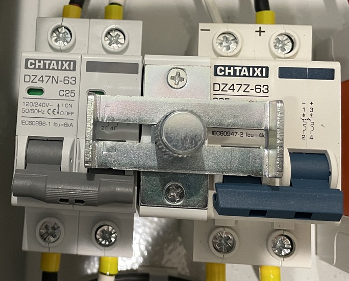 Yup, when you want to lock out all incoming power from the genset or the PV array it turns into a “lock out”. Yeah, yeah…I know there is no place for a true padlock or even a tag to prevent sliding the interlock into operational capability. But, for me it is just a cool feature for added safety…not ultimate safety.