TIP : Solar – Check/Tighten All Connections…regularly

A dangerous, potentially catastrophic, situation developed with my solar system and I was almost unaware of it. Thankfully I caught it in time and learned a couple lessons along the way. And that is what I will share with you today.

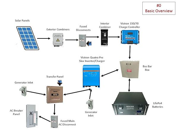
I run a 150/70 Victron MPPT SmartCharger…a charge controller that converts the solar panel power into usable power that charges my batteries and provides power to the inverter during daylight hours. The 150 represents the incoming 
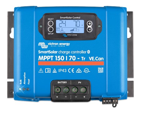
voltage from the solar panels, the 70 represents the amperage (current) going into the inverter and batteries.

Normally we push about 82vDC from the panels into the charge controller. And the charge controller runs about 45 – 50amps into the batteries/inverter under normal conditions. It can run a high as 70amps in early fall or on some summer days. In the winter it can go as low as 35 – 40amps due to the solar elevation. Obviously it can go down noticeably as cloud cover increases.

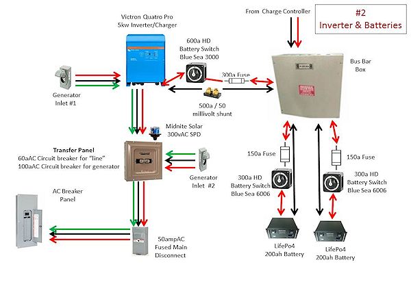
When I installed the charge controller I used a standard wire size calculator for 70a, less than 10’ (round trip) circuit. That showed that 6AWG wire was plenty good enough, well within the requirements. And I wanted the 
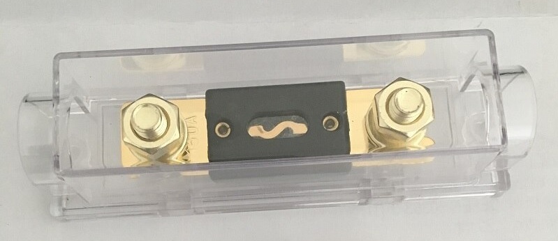
circuit fused to protect the charge controller and the rest of the system, so I went with an 80a ANL fuse. And since I didn’t want the wire to act as a fuse I upgraded the wire to 4AWG, which is capable of 80a when used in a less than 15’ (round trip) circuit. Yup, all set!

About 2 months ago I was looking over the system on a particularly sunny early fall afternoon with the sun at the perfect solar elevation for my panels. I was hitting the 70a max for the charge controller. But not to worry, the charge controller will throttle the output amperage at 70a and not let it go above that limit. It does that by limiting the input power from the panels. Well, something prompted me to touch the 4AWG wire between the charge controller and the ANL fuse. Ah…hot!

For some reason, and I mean unknown, I had used 2AWG between the main busbar and the ANL fuse, but used 4AWG between the fuse and the charge controller. Please don’t ask me why, I don’t remember. I probably ran out of 2AWG and didn’t want to go buy a 1’ piece of 2AWG…but I wasn’t worried about it because 4AWG was a full size above what was required anyways.

But the 2AWG wire on the battery side of the fuse was not hot at all. Hummm….. I wrote it off as being the peak 70a current due to the sun intensity, panel angle, and solar elevation. A month later I was looking over the system again and noticed a slight discoloration to the 4AWG wire, I touched it, it was real warm, not hot, but real warm. The 2AWG below the fuse was room temperature. Problem! But I couldn’t figure it out, not to worry, the fuse would protect the system no matter what…and it was high quality 105c degree rated insulation on the wire so I wasn’t particularly.

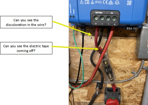
A couple of weeks later I was once again looking over the system and noticed my red electrical tape on the aforementioned 4AWG wire, used as makeshift heat shrink, had flagged on me and an end was sticking out. 40A current showing on the charge controller and the wire was real warm. OK, I am not the brightest bulb on the tree but I realized I had to cure this problem. I wasn’t sure what the problem was…but it had to be fixed whatever it was. And since I didn’t know for sure what the problem actually was, it was my intention to replace the 4AWG wire with 2AWG, new terminal lug, proper heat shrink, and replace the 80a ANL fuse, maybe even the fuse holder if needed.

Now…left turn for a minute. While researching my upcoming system upgrade I learned that using wire ferrules on the battery wire going into the charge controller is considered “best practice” for a number of reasons, all of which made perfect sense. So I was sure that my wire overheating came from that lack of wire ferrule when I first put the system together 2.5 years ago. I now have the tool and wire ferrules…this “fix” would be a great trial run for me.

Well, the day came for the “great fix”…full batteries, informed the wife of the need for low power consumption, and gathered all of my tools and parts. Shut down the panel power input, disconnected the batteries from the charge controller, tested all the wires to make sure the charge controller was isolated, and double checked everything once again.

I went to disconnect the charge controller to battery ring terminal from the fuse and immediately knew what the problem was.

About a year ago I was reading on how to maintain a solar system and one of the points made was to check all electrical connections, then tighten or replace as needed. Ah, well, the nut holding down the ring terminal on the charge controller side of the fuse was actually loose. Yup, loose…and that was the problem.

You see if a terminal connection is loose it becomes a high resistance connection and that generates heat. The hotter the terminal gets, the weaker it becomes, and this continues until it shows up as a critical failure. But the question remains…why did it become loose? I know for a fact that when I did the initial install I tightened it correctly…period. But, as I thought about it…all the times the ring terminal connection heated up, then cooled down, then heated up, then cooled down…over and over again nearly 2,600 times. The nut simply loosened itself due to the continuous heating and cooling. And I never once checked my connections to see if everything was still tight.

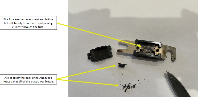
Well, I replaced everything as needed, making sure everything was properly tightened. Everything is fine now, the system is running as designed, wire is room temperature, and I am sleeping a little better. Then I took the old fuse apart this morning. Oooooppppppsssssss…

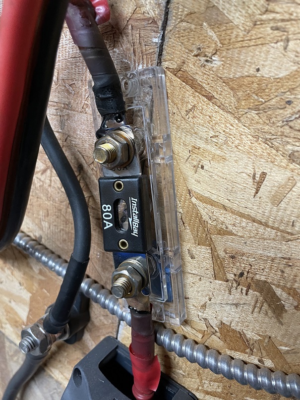
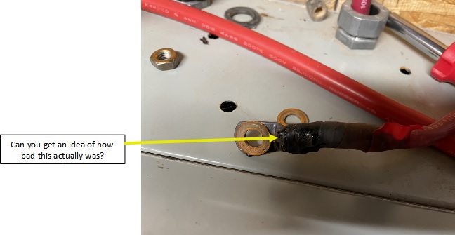
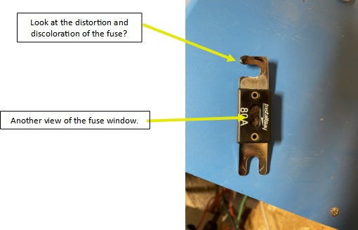
See the picture for more information, but, the fuse was burnt as it should be but not 100% separated at the element. Thus, current/power was still flowing to the batteries/inverter but was several impeded.

Needless to say…I will be setting up a schedule to perform maintenance just as advised.


 2009 - 2022 Copyright © AHTrimble.com ~ All rights reserved
No reproduction or other use of this content 
without expressed written permission from AHTrimble.com
See Content Use Policy for more information.

Our Glamstead Solar System

Here we go…I was asked to supply the info and diagram of our solar system. I hope this can be of use to folks who are thinking about going off-grid or grid-tied.

After working through the numbers I felt a 4kw – 5kw inverter would handle our needs. Yeah, I maybe didn’t get it right…thought it would meet our needs.

Later I thought about adding electric baseboard heaters…right after I figured out we needed air conditioning. So be careful on how you calculate your electric needs…then add 40 – 50%.

So here are “jpgs” for each part…

Here is the link for a PDF file of the whole thing…

< click here for Glamstead Solar Sytem PDF file >


2009 - 2022 Copyright © AHTrimble.com ~ All rights reserved
No reproduction or other use of this content
without expressed written permission from AHTrimble.com
See Content Use Policy

TIP : Very Energy Efficient Air Conditioning for Solar Systems

As you know we have a solar system…3.8kw Canadian Solar PVs, 400ah LifePo4 batteries, 5kw Victron inverter powering a 120vAC household system. Originally we were not going to have air conditioning…but a summer of me building the house changed my mind quickly. So the next summer (2020)…we had an older standalone upright AC unit that we pressed into service. Mistake! Terribly inefficient, power hog, loud enough to make conversation uncomfortable, and didn’t get the house below 80 degrees.


The issues/problems that we faced were:

  1. Not enough AC power for a regular whole house AC system.
  2. Only 120vAC power.
  3. 915sq’ of living space in 4 rooms (master bedroom, spare room, bathroom, & great room that includes a kitchen).
  4. Not enough available wall space for a split unit.

Bottom line…we had little other choice than a window unit. But they are notorious for being anything but energy efficient as well as being limited in total square footage vs BTU…not to mention noisy. As I said…few options…limited selection…yuck. So into research mode I went.

I found inverter technology as an alternative to standard air conditioner technology. So what is this inverter technology? Basically is converts incoming AC power into DC power. Then it regulates that DC power to the unit through a modulation process. Meaning…it only uses the bare minimum power required at the time for the temperature setting vs room temperature. And since DC power is more efficient on electric motors and compressors you get longer life out of them as well. The result in power savings is around 35%.

And as an added benefit I found a unit that is 9 times quieter than traditional AC units. Yeah, quiet as a library. Nice!

Now it was time for a trial…we decided to try it out on our 224sq’ master bedroom…after all a decent night sleep with AC is worth a whole lot!

We purchased a “Midea 8,000 BTU U-Shaped Smart Inverter Window Air Conditioner” for our trial run. It was rated to cool 350sq’ giving us a 40% margin…meaning that the AC unit should be able to 100% cool the room running at 60% capacity. We bought it from Amazon for $389 (tax included).

It was very easy to install, very quiet, super energy efficient, and froze us out 🙂 We considered it a success in every way. It was even quiet enough to allow me to sleep uninterrupted, and that is rare for me. So we bought the second unit a month later. This time we bought a 12,000 BTU unit (rated for 550sq’) for the great room / kitchen which is 460sq’… for $465.

It was a very nice summer & fall and the solar system could handle the power load with no issues. We even ran it into the night till 10:30 a couple times…still over 80% on our batteries.

This year when I put them back into service I placed the 12,000 BTU unit in the great room again but a different window that was protected and shaded. The 8,000 BTU unit went into our spare room which opens into the hall that opens into the bathroom, the master bedroom, and the great room. So far we are super pleased with the AC cooling power set-up we now have. And we don’t even have to run the AC’s after sunset…if that long.

Why not put the AC unit back in the master bedroom? Well, it was in my window the summer before so no cool breezes for me at night. This year…ahhhhhhhhh…cool summer night breezes every night through an open window.

We do have ceiling fans in the master bedroom and the great room / kitchen that keeps the cool air moving. I contribute that to the master bedroom staying at a very comfortable temperature all day.  We usually keep the great room / kitchen set at 71 degrees and the spare room set at 67 degrees. This keeps the whole house very cool and comfortable.

The maximum AC power draw on the 8,000 BTU unit is 8.75 amps and the 12,000 BTU unit comes in at 12 amps. However, when I look at the user screen on the solar system computer I rarely see them drawing more than about 8 – 12 amps total combined. So realistically, if I have them both running, they are drawing no more than 21 – 30 amps off the batteries at any one time. Considering that the PVs are producing 50 – 70 amps during the day…I am getting free AC and still charging the batteries.

I love these AC units! They are super energy efficient and very, very quiet. If you have a solar system and no AC but you want AC…these are the units for you! If you currently use grid power and have older energy inefficient window AC units…you might want to consider upgrading to these units.

Unit information:

  • ULTRA QUIET – The Midea U Smart Inverter AC unit is 9 times quieter than traditional units. The U-shape design uses your window to blocks noise outside and the high efficiency Inverter system warrants ultra low noise and vibration. This design allows for extremely quiet operation as low as 42 dBA – almost as quiet as a library – so you can get a restful night’s sleep or binge your favorite shows undisturbed.
  • MORE THAN 35% ENERGY SAVINGS – With the advanced DC Inverter technology, Midea U achieves over 35% energy savings compared to other traditional units, and it’s the first window AC to obtain the ENERGY STAR Most Efficient 2022 Certification. You may also get exclusive benefits from your local energy distributor.
  • FLEXIBLE WINDOW OPENING – Midea U-shaped design allows your window to open, bringing fresh air into your home anytime and allowing you to maintain more of your view even when the unit is installed. The Anti-Theft Mechanism locks the closed window for added security
  • SMART CONTROL – The Midea U Smart Inverter Air Conditioner is Wi-Fi enabled and can be controlled from anywhere through the cloud using the MideaAir app on iOS or Android. You can also use voice commands throughout your house, office, or apartment using Alexa or Google Assistant.
  • ROBUST INSTALLATION – Install the included quick-snap bracket, set the unit on the bracket, and secure the sidearms. After that, you are all done and ready to enjoy. Available for single-hung or double-hung windows with size: 22″-36″, minimal height at 13.75″.

For the 8,000 BTU, 350sq’ unit < click here >

For the 12,000 BTU, 550sq’ unit < click here >


 2009 - 2022 Copyright © AHTrimble.com ~ All rights reserved
No reproduction or other use of this content 
without expressed written permission from AHTrimble.com
See Content Use Policy for more information.

TIP: Prepping for Electrical Issues

This is actually a sub-article to a larger project article and it includes some items from previous articles. However, I think there is a solid case for writing this article as a stand-alone. Wow…mouthful of word salad!

So there I was…time to finally upgrade my water well system to a solar pump water well system. You can read more about it here <click here to read about it>. It came time to do my wire splicing…and that is where this article came from.

During an emergency, disaster, or grid-down event you may find yourself having to do some electrical work. And if you find yourself having to do some splicing it would be nice to have the needed supplies on hand. Here are a couple of things that I feel could be invaluable in those situations.

Let’s start with the basics…Electrical Tape –

Not all electrical tape is created equal. And let’s start this off with a general statement…you get what you pay for. That means I buy Scotch brand electrical tape, or private label electrical tape made by Scotch. I don’t buy the knock-offs or the cheap stuff. Why? Because I am entrusting personal safety and/or my house and/or my equipment to this electrical tape…I don’t want cheap-junk vs expensive-quality. Nice thing is…the quality stuff isn’t really that much more expensive.

I keep three basic types of electrical tape on hand; 1) Scotch 700, 2) Scotch 2242, 3) Ace 30986.

Scotch 700: A high quality, vinyl insulating tape. Resists a wide range of chemicals and abrasive materials. Can be used indoor/outdoor and even below ground. And a roll has about 66’ on it. It is good down to about 15 degrees or so. Pretty much a general purpose electrical tape that I would use where the tape is not exposed directly to the weather and not exposed to moisture…so basically dry indoors. Don’t over stretch this tape when using.


Scotch 2242: A high quality general purpose rubber tape. Used correctly it provides an immediate moisture resistant seal as well as insulation. This is a great weather resistant electrical tape. Stretching doesn’t really affect this tape. Since it is made out of rubber it is pretty dang resistant to abrasion. It is good down to about 0 degrees. A bit more expensive and only 15’ on the roll. This what I would use when the job was exposed to the weather or on my equipment (i.e. tractor) used outside.


Ace 30986: Self-fusing, water-tight, rubber based electrical tape. It seals based on a rubber resin, “vulcanized” as my electrician buddy explained it to me. It is pricey but well worth the money when a water-tight seal is needed. This is the tape I used to protect the splices on my well pump installation. Yes, that means the splice was submerged in water…and will be for years to come. I used multiple layers, medium stretch, pressed together hard.


I also keep two types of Gardner Bender Liquid Tape on hand; 1) the brush on variety, 2) spray on version.

Brush on version (GB LTB-400): It’s a rubber based brush on electrical sealant. It can be sued indoors/outdoors and creates a waterproof seal when used correctly. It’s also very UV resistant which is nice here in Arizona. It is resistant to chemicals, solvents, and saltwater. It is dry in 5 minutes, fully cured in 24 hours. Can be used in harsh temperature conditions…30 degrees below zero to 200 degrees above zero. And it stays pretty dang flexible. I like it when I use butt connectors and want to make a water tight seal around them.  If I wanted a really good, virtually fool-proof water tight seal I would use the Ace 30986, then use two coats of GB LTB-400 allowing 24 hours between coats. First coat of GB LTB-400 would overlap the Ace 30986 tape ends. Then the second coat of GB LTB-400 would overlap the first coat of GB LTB-400. WARNING: don’t think an opened container of the GB LTB-400 will be acceptable for storing! Once opened it tends to dry out. Store a brand new, unopened container.

Spray on version (GB LTS-400): This is kinda like the brush on version, but not entirely. This stuff is vinyl based vs rubber based and is much thinner obviously since it is sprayed on. Yes, you can spray on multiple coats to build up the thickness. It dries quickly (5 minutes) and is fully cured in 24 hours. It is very protective and insulating but I would not count on it being water-tight with a single application, more like water-resistant. Water-tight if you build up multiple, correctly applied layers, each of which is allowed to properly cure. Can be sued indoors/outdoors and a temperature range of 30 degrees below zero to 200 degrees above zero and resistant to chemicals, solvents, and saltwater.

So there you go…there is my electrical prepper kit for electrical work.


Related Articles –


 2009 - 2022 Copyright © AHTrimble.com ~ All rights reserved
No reproduction or other use of this content 
without expressed written permission from AHTrimble.com
See Content Use Policy for more information.

Super PWRgate PG40S Auto-Switch

Ham In The Box - Super PWRgate PG40S by West Mountain RadioSometimes you just need that right piece of gear, that one need that is weird to fill, but you need it…you really, really need the right piece of equipment..

Well, the West Mountain Super PWRgate PG40S Auto-Switch is one of those pieces of equipment. And then some! Yeah, it’s that flipping good.

Let me share a little background first. For several years now I’ve been working on putting together radio and power equipment to keep communications going during emergencies, disasters, especially during a grid-down. Why? Other than the obvious answer, during my 30+ years of responding to emergencies and disasters I’ve learned that stable and reliable communications is a top priority. How much so? In every single incident where a firefighter was injured or killed, communications (poor or lack of) played a major role. Communication problems were the single common thread through all of these incidents.

Now, let me change to something completely different for a minute. I’ve been around long enough to remember the first personal computers. You know, the kind that didn’t even have a hard drive. I remember several times I would be working on these early computers and the power would flicker…everything lost! Yup, all the work that I had been doing was gone into some special “data zone” never to be seen again.

Finally after that happened a couple of times I learned about uninterruptible power supplies (UPS). Through pure magic it kept your computer going even when the power, not just flickered, but went out completely. It was as if the computer gods decided to smile down on us mere mortals. Yeah, I didn’t know at the time is was just a battery, auto-switch, and a battery charger built into that wonderful, magical UPS box.

Now, fast-forward to today…during times when communications are needed most I don’t want them to fail just because the power suddenly, unexpectedly flickers or goes out altogether. Because…DUH…during emergencies, disasters, and grid-down the power should be expected to go out! Yeah, no-brainer right?

Well, to meet the uninterruptible power supply needs that I foresaw, it would take a whole lot of money to buy the right UPS. And even then it wouldn’t have all the options and features that I wanted. So naturally I decided I was going to build my own solution. No, I am not a masochist, I just like to use my brain, to be challenged, and work with my hands. So, another great adventure was headed my way!

As I began to layout my first power box I had written down my “mission statement” for the box itself. Then I listed the “restrictions and requirements” that went into great detail. One of the biggest needs was the ability to automatically switch from the AC to DC power supply to the battery supplied DC power. The quest began!

Here is the mission statement for this piece of equipment –

“Provides clean DC power from an AC power source and automatically switches to battery back-up providing DC power when the AC power fails.”

I gotta tell you…it wasn’t hard to figure out. As usual I started doing some serious research into the options available out there on the market. And it became clear real quick that there was a pack leader, a unit that simply stood out among the others in terms of reliability and quality…West Mountain Radio’s Super PWRgate PG40s.

Here is the technical story from their website –

  • A Super PWRgate is a 12 volt backup power system rated at 40 amperes continuous from either a Power Supply or a Battery.
  • The Super PWRgate has a built-in four-stage battery charger with selectable current rates of 1, 4, 7 or 10 amperes.
  • Connected equipment will instantly switch to battery during a power blackout or power supply failure.
  • Uses two 80 ampere Schottky diodes as an OR-Gate to isolate the battery and power supply from each other.
  • Low loss PWRgate provides forward voltage drop of less than 0.3 volts at 20 A and 0.37 volts at 40 A.
  • Optimized for use with GELLED & AGM type batteries, but will keep flooded lead acid and marine type batteries near full charge as well.
  • Solid, durable construction in an aluminum case with heat sink. Includes mounting holes for convenient and secure use in mobile units.
  • Uses Anderson Powerpole®connectors
  • Dimensions: 1.65″ H x 5.25″ W x 3.9″ D

Specifications –

Maximum Voltage: ·                     18 Volts DC
Maximum Current: ·                     40 Amperes
Circuit: ·                     Diode OR-Gate
Diodes: ·                     Two Schottky 80 Ampere, 20 Volt
Voltage Drop: ·                     0.25 VDC at 1 Ampere

·                     0.37 VDC at 40 Ampere

Charging Circuit: ·                     Smart, linear charger

·                     Fuse switched for 1,4,7 or 10 Amperes (±5%) maximum

·                     Peak voltage limit: 13.8 (Gelled), 14.2 (AGM), (±2%)

·                     Peak voltage limit set via internal jumper to GELLED or AGM

·                     Peak voltage terminate point: 0.1 Maximum current

·                     Float Voltage: 13.5 volts (±2%)

LEDs: ·                     Green – Indicates charger is “ON”

·                     Red – Indicates peak “PK” charge voltage

·                     Yellow – Indicates Float “FL” voltage

Connectors: ·                     Anderson Powerpole, 40A
Dimensions: ·                     1.65″ H x 5.25″ W x 3.9″ D
Weight: ·                     0.9 lbs, 0.4 kg (aluminum enclosure with heat sink)
Mounting Holes: ·                     Two, 0.175 in. d, at a distance 4.875 in., for #8 hardware


Typical application –

Findings –

  1. I couldn’t get the unit to fail when switching from the power supply to the battery. No matter what I tried it performed the power switching perfectly. There wasn’t even a flicker in any of the equipment I tested it with.
  2. It really does a great job of keeping a battery charged. Technically that makes it a battery “maintainer” and not so much a charger. But, I ran my big 100Ah battery kind of low, then let the PWRgate go into charge mode. Yup, performed flawlessly; the unit didn’t even get hot.

 Summary –

This is a high-quality product that does exactly what they say it is supposed to do…and what it needs to do. For my radio set-up it is an essential piece of equipment and I am 110% satisfied with it. Awesome job West Mountain!


2009 - 2020 Copyright © AHTrimble.com ~ All rights reserved
No reproduction or other use of this content 
without expressed written permission from AHTrimble.com
See Content Use Policy for more information.

AIMS Power (PWRI60012S) 600W Pure Sine Power Inverter

note: article first appear April 2016

I hope by now you are familiar with the “power box” that I built. Some might call it a “solar generator” but it is way more than that. Since this power inverter review will tie directly into the power box, it might be a good idea to read the power box article first.

< Click here to read about the power box >

The whole concept of this “power” thing is to make sure that during emergencies, disasters, and grid-down that you have enough electrical power to accomplish your essential mission(s). For me, “essential mission” is basically recharging batteries to keep my radios operational and my tactical lights running. No, it is not to keep the air conditioning running or the freezer on. I don’t consider those two things as essential.

The mission statement –

“To provide sufficient ‘clean’ power to run, or charge batteries for, essential sensitive electronic gear that requires 120vAC power.”

Requirements & Restrictions –

  • Must be “clean power” to not damage or destroy sensitive electronic equipment.
  • Must be able to handle surges of at least 50 – 150% of the unit’s continuous rating.

As always I did considerable amount of research before I identified the units I would be testing. This Aims unit really looked good from all the details and information I could gather. I also tried something different this time. I contacted the company and told them I was doing an evaluation of power inverter units under emergency preparedness conditions. I asked them if they would like their unit included. I figured if they didn’t think their unit could handle the testing and subsequent review that they would back away. They didn’t…the unit tested showed up about two weeks later. I think that showed considerable confidence in their products.

When I pulled the unit out of the box the first thing I noticed is the unit outer housing is a giant heat sink. That is important to see that their engineers understand the necessity to move heat away from any power inverter. Then I turned it over a couple of times in my hands and saw that the unit was very well built with attention to detail. After all these years I can often tell by the “feel” of a product if it is junk or quality. The Aims unit felt like quality in every aspect. My testing proved me right.

The + / – battery connections on the back of the unit weren’t Anderson Powerpoles and that was kind of a drag, but I didn’t really expect them to have Powerpoles as a connection option. The unit’s connectors were solid and the connection faces were exactly flush with each other which will ensure a good connection with the “eyes” on the power wires coming from the 12vDC power supply. The plan is I will make my own using #10 wire and high-quality ring connectors, along with in-line fuses. Yes, the unit has fuses built in, but I would rather protect the unit well before the unit’s fuses themselves.

The fan located on the rear of the unit is meant to keep the unit cool when under load. However, it isn’t always running. The fan will start up when the unit is outputting about 100w. That is a nice feature because the fan does take power to run…precious battery power. If you are using a low consumption device that doesn’t exceed 100w then you are draining additional power with the fan running. But the fan is there when you need it. Sweet! They designed this thing to be very stingy using power from the battery.

I also noticed that there is separate ground connection. No, not the negative terminal connection, but an actual ground connection. I am no electrical engineer but I know enough that grounding an inverter is a good piece of advice. Having the inverter unit itself grounded (PE) provides protection from a number of “faults” and protects your electrical devices running off the inverter.

Basic Hook-Up Diagram –

Dang…there are so many things I could talk about in regards to this unit. There are so many features and protections that I am almost overwhelmed with how much to write about. Let me give some technical details from their website about this unit first…

Features –

  • 600W continuous power, 1200w surge
  • Pure sine wave
  • USB Port, 5v, 1a
  • Dual 120vAC receptacles (3-prong)
  • On/off rocker switch
  • Over temperature indicator
  • Overload protection via fuses and automatic shutdown
  • Low battery voltage warning/shutdown
  • Alligator clips included on 28″ of heavy-duty wire
  • High input voltage protection with automatic shutdown
  • Over load indicator
  • Short circuit protection
  • Load based fan – only runs when an inverter senses a load over 100w

Technical Specifications –

  • Continuous output power: 600 Watts
  • Surge power capability (peak power): 1200 Watts
  • DC input / operating voltage: 9.7 to 15 Volts
  • Output voltage: 120 Volts AC
  • Output voltage regulation: +/- 3%
  • Output wave form: pure sine wave
  • Output frequency: 60 Hz
  • Battery low voltage shutdown: 10.0 +/- 0.5 Volts
  • Low battery voltage warning/shutdown
  • No load power consumption: < .6amps DC
  • DC amps: 50
  • AC amps: 5
  • Full load efficiency: 90%
  • 1/3 load efficiency: >85%
  • No load minimum operating temperature: 50 degrees
  • Full load maximum operating temperature: 145 degrees F (automatic shutdown)
  • AC Output Sockets: dual Type 2 -3 prong and single USB Output
  • High input voltage protection: 15V
  • Low input voltage shutdown: 10V
  • Internal blade fuse protection
  • Product size (L x W x H): 9″ x 6″ x 3″
  • Weight: Unit: 4.4

Voltage Handling –

  • When your battery drops to about 10 – 10.4vDC a low voltage alarm will sound. No, it won’t blow your ear out, it is subtle but clearly noticeable.
  • When the voltage then drops to 9.7 – 10vDC the unit will automatically shut down. This feature operates exactly as a LVD (Low Voltage Disconnect), and that saves your battery from over-discharging and being damaged. Actually, 9.7vDC is really a pretty low level to draw your battery down to. You don’t want to do it very many times.
  • The unit also has a shutdown feature for the high end as well, 17vDC. But, if you are running 17vDC into the unit you have much bigger problems with your 12vDC battery powered system. However, the transformer that I use in “My Power Box” can push out up to 16vDC (variable control). So, it is nice to see that the Aims inverter can handle up to that voltage rating. I guess the real purpose high-voltage shutdown feature is to prevent the unit being damaged by being accidentally hooked up to a 24vDC battery system.

Operating Environment –

  • This unit is not meant to run in all conditions and locations that exposes it to certain environmental elements. This unit is meant to be protected from those elements.
  • The temperature should be between 32 – 104°F. Yup, that means not below freezing and not desert SW June daytime direct sun temps. I am not understanding why the low temperature restriction and I have contacted Aims for an explanation. Aims AnswerThe reason it is rated at 32F is  there is silica and ceramic based components inside when those components run below freezing and warm up during operating they tend to crack and will cause failure.  Another point is that you lose efficiency, a lot of efficiency, at these temps, everything is working harder.  
  • The unit has to be ventilated under all circumstances. This is a piece of electronic equipment that generates heat, you have to be able to move that heat away from the unit. That just means to allow enough room around the unit to make sure air can circulate.

Uses –

Here is what Aims is listing as potential uses for this inverter –

  • Laptops,
  • YVs,
  • DVD players,
  • CPAP machines,
  • Satellite TV systems,
  • O2 concentrators and generators,
  • Mobile office set ups,
  • Fast charging power tool batteries (like my Ryobi 18v power tool chargers)
  • Other small hand held electronics

I am using the Aims power inverter for charging my handheld radios, electronic gear (computer), small appliances, etc. From DC power generated either from my truck or from my power box. For heavier AC loads (i.e. power tools) I use my Honda i2000EU generator. Aims does have much larger pure sine wave inverter units, up to 4000watts. I would love to test one of those higher wattage units but I just don’t have that requirement at this time.

NOTE: One thing I really want to point out…Customer Service. When dealing with Aims I was really impressed with their fast responses to any question I had. They appear to be very solid people, dedicated to both their products and their customers.

For my potential needs this unit exceeds all my expectations! I am giving this sweet little unit a “Buy!

600 watt version


1000 watt version


1500 watt version


2000 watt version


3000 watt version


4000 watt version


2009 - 2020 Copyright © AHTrimble.com ~ All rights reserved
No reproduction or other use of this content 
without expressed written permission from AHTrimble.com
See Content Use Policy for more information.

MFJ 4230MV Compact 25a Power Supply

MFJ-4230MV COMPACT SWITCHarticle first appeared in June 2016

I love mobile radios! So far I have –

  • Yaseu FT-8800R
  • Yaesu FT-8900R
  • Yaesu FT-897D
  • Yaesu FT-2900R

Told you I like mobile radios! And yes…I like Yaesu brand mobile radios the most.

But, having all these mobile radios I need to be able to power them when I am outside of the truck. And the only commonsense way to do that is with stable and readily available AC power from the utility company. But, a little tiny bit of a problem…the radios all run off of 12vDC power.

OK, so it is really no problem at all…you just use a power supply. Technically it is a “transformer” if my memory serves me right. You are taking 120vAC voltage -and through the magic of electronics- transforming it into 12vDC power. And that DC power can be used to run your mobile radios without a vehicle battery.

As always…my mission statement –

“Provide clean, stable, reliable DC power from an AC power source to run one or more mobile radios.”

Requirements and Restrictions –

  • Must not induce “noise” into the radio on any band above an acceptable (minimal) level.
  • Must be able to work continuously for years at a time without being turned off.
  • Should generate minimal heat when in stand-by mode.
  • Should generate manageable heat when being used continuously.

Well, here is the deal…I had already been using an MFJ SWR meter and I liked it a lot. My first power supply was from Radio Shack and it performed really well and I had no complaints. However, it just didn’t push enough amps (power) for my new usage requirements. So I naturally looked to MFJ for a power supply option. I did my research and the 4230MV unit appeared to meet all my needs/demands. Then it was time to do my research.

I carefully read all the reviews I could get my hands on. I really dug into it. What became obvious to me from the beginning was a couple things:

  1. The overall price point was excellent. Same could be said for the “price to amp” cost.
  2. Users were reporting no real “noise” on the HF or any other bands.
  3. It was one of the most compact units on the market.

Here is some technical information –

  • 30 Amps Surge (up to 5 minutes), 25 Amps Continuous.
  • 4 to 16 VDC adjustable output, detent at 13.8VDC.
  • Light weight, only 3.4 lbs/1.35kg
  • Compact, only 5″ x 2 ½” x 6″ (W x H x D).
  • Backlit meter that displays amps or volts.
  • Five-Way binding post for high current radios
  • Over Voltage protection.
  • Over Current protection with “FAULT” LED.
  • QUIET Internal Cooling Fan with “FAN” LED
  • Super Regulation, works with AC input from 85 to 135 VAC (115VAC model) or from 170 to 260 VAC (230VAC model), 47-63Hz
  • Noise <100mV. AC Line Fuse( 6.3 Amps)

Findings –

I purchased my first unit several years ago and began my testing. Let’s not make this difficult…it performed exactly as it was advertised and met 110% of my expectations. Yup…a great little unit. But, let me give you a few more details –

  1. The unit will warm up a bit when using it continuously. There is a cooling fan that will spin up initially when you turn on the unit, then shut-down. Then it will come back on at about 70 degrees. It seems to spin faster as the temp rises. There was minimal sound from the fan, no problem at all.
  2. I could detect no noise on the HF side or any other band.
  3. While the unit is rated at 25amp, it can handle 30amp surges with no problem. But, it won’t operate continuously at 30amp.
  4. I’ve seen folks who have been running this unit for 3 – 4 years with ZERO problems.
  5. I like the adjustable vDC output, gives you some nice operating capability options.
  6. I really like the clean face of the unit. It may sound silly, but it looks very professional. And I like that look sitting there on the shelf while it is working away for me.

Summary –

A great power supply unit!!

Yeah, there are some folks who like to poke fun at MFJ from time-to-time…but don’t buy into that. MFJ has a 1-year “no matter what” warranty. And that is very reassuring and tells you how confident they are in their equipment. Think about it…if a piece of electronic equipment it going to breakdown to poor quality it will probably do so in the first 30 days, undoubtedly within the first 120 days. MFJ has your back!


2009 - 2020 Copyright © AHTrimble.com ~ All rights reserved
No reproduction or other use of this content 
without expressed written permission from AHTrimble.com
See Content Use Policy for more information.

I apologize…

Without realizing it till yesterday, my Power Box Project articles were posted without editing and without pictures. I apologize for that mistake. I got sidetracked with the SitRep – 05/01/20 – WARNING ! and all the Immediate Action Warnings. I have gone back and did some quick editing and added the associated pictures to the 3-article series My “Power-Box” Project.

Please take the time and review those articles again.

Click to start reading the first article…


My “Power-Box” Project – Part #3

Time to finish the portable power box!

I finished up Part #2 showing how I built the basic box and wired it up. In this article I will show you how I finished wiring it and then added a great option. OK, I think it is a great option. And, I will include a really basic wiring diagram. No, I am no electrical engineer and the diagram won’t be some high-grade schematic, but it will clearly show you how I wired everything. And hey, remember…it all works…and works really well. A little secret…I made some changes to the wiring, but not to worry, I will explain the changes.

< Read Part #1 by clicking here >

< Read Part #2 by clicking here >

Here are some of the additional options I wanted to add to the power box-

  • Distributing higher amperages,
  • Distributing a “cluster” of outlets on an extension cord,
  • Using a heavy duty battery charger to charge the internal battery, and
  • “Daisy-chain” boxes together for more ampere hours.

As I was thinking through the additional options I wanted, I figured I needed heavier gauge wiring than just #10. And I also wanted really well protected wire outside of the box to protect against heavy-duty usage. So I naturally gravitated to my standard…Anderson Powerpoles…the PP75 option seemed as if it was made to order for my application.

Anderson Powerpoles
Powerwerx PP75

For my wire I followed my own advice…I went to Walmart and purchased a set of 12’ booster cables in 8 gauge wire. Cheaper than buying the equivalent wire and it comes with much heavier-duty protective insulation. I snipped off the clamps, installed the PP75 connectors and my “extension cord” was good to go.

Next came the wiring from the battery “through” the box itself. I wanted it to be a “through the chassis” connection vs. just laying out the extension cord. And it had to be fused since this was going directly to the battery vs. through the distribution block that I also installed since the last article. The extension cord would not be going through the PWRgate since it is designed to handle much higher amperages than the 40amps of the PWRgate. And I didn’t want to fry the PWRgate by sending voltage in a reverse direction through the PWRgate into the battery.

To make this connection I started with a fused connector from Powerwerx – MAXI Fuse Holders with Ring terminals and 75 Amp Powerpole Connectors.

Powerwerx RGH-08

It is a heavy duty 8 gauge fuse holder with 40 amp MAXI fuse – 75 amp Powerpole connectors on one end and gold plate 3/8 inch ring terminals on the other end. It is their item # RGH-08.

To make a solid “through the chassis” connection I went with the Powerwerx Powerpole Mounting Clamp, item # 1463G1. I wanted the connection in the vicinity of the other connections simply for convenience. So I located the right spot, measured the right opening size, and cut it out.

Powerwerx Powerpole Mounting Clamp, item # 1463G1

Note: don’t make the opening too large. You want it to be a tight fit to lock the connectors into the mounting clamp and firmly against the box material as well.

I secured the top plate first making sure that the fit was very tight to the box.

Then I drilled my holes and secured the lower plate. Make sure you have a solid fit! You must have a solid fit so the connector doesn’t come loose when plugging and unplugging the extension cord.

Bingo…done! I had my 75amp heavy duty connection made directly to the battery. I now had my options. First was simple attaching the extension cord to another box. I want to hook the batteries up in parallel to increase the “capacity” so the extension cord is already made correctly… positive to positive, negative to negative.

Power Box with 75amp extension cord.

I also wired up a couple of battery clamps to a set of PP75 connectors. Now, I can connect the box to another battery directly. Note: the Anderson Powerpoles make it virtually impossible to make revers connections damaging electrical components.

I also had a Powerwerx PS-75-45-4 in my parts box to connect to the end of my extension cord. Now I could run my extension cord 12’ add the PS-75-45-4 and connect four devices to the extension cord. Devices such as four radios, etc.

Power Box with 75amp extension cord plus the options of battery clamps and the Powerwerx PS-75/45-4 power distribution block.

Note: Be aware that the Powerwerx PS-75-45-4 is no longer being made but can still be found at suppliers such as GigaParts. Powerwerx has a replacement option called the “PD-75” which will accomplish the same thing.

Now my power box is ready to go to the field!

In my next article in this series I will share a few of my ideas on how to use the box. And for those of you that are wondering…yes, this could be considered a “solar generator” when connected with solar panels for charging. But, yes again…it is so much more than just a simple “solar generator” if you think through the possibilities.

Power Box wiring diagram.
click the image to enlarge

Download the wiring diagram in a PDF < AHTrimblePowerBoxWiringDiagram>


2009 - 2020 Copyright © AHTrimble.com ~ All rights reserved
No reproduction or other use of this content 
without expressed written permission from AHTrimble.com
See Content Use Policy for more information.

My “Power-Box” Project – Part #2

After starting, stopping, starting again, stopping once more…then putting the project on hold it was time to get back on this project. Does that sound confusing enough?

Well, when I started building this power box project I had this grandiose idea of having all these levels of redundancy and just a heck of a sophisticated power box. Yeah, remember what the KISS principle is? Well, somewhere along the way I went brain dead.

< Read Part #1 by clicking here >

Now, in my defense, the original power box that I had built worked! It had three batteries, a PWM solar charger built in, a relay to cut-over to a second bank of batteries should the big 100Ah AGM battery drop too low. There was an auto-switch from AC to DC if the AC failed. And there was more, much more. But, when I was all done with it, it simply was way, way too much…too sophisticated.

So I sat there in my shop one evening and was looking over the power box monstrosity thinking I had developed the perfect Frankenstein Monster. But, perfect in regards to theory only. In the field it would be too heavy, too many electronic parts, too complex, and just the wrong thing for the job. So, what did I do about it? I went back to basics. I reviewed the original “mission” and then went over the “Requirements & Restrictions.” Then it became clear to me to stop trying to overkill it.

Once I made up my mind to go back to the basic use I thought I should jump on it. Yeah, life had other plans for me, I was buried in other projects and it was just too cold out in my shop so I put the whole thing on hold till it got reasonably warmer. That was last week.

Once I started back on the project it went quickly and easily. I just wanted a power box that could –

  1. Provide reliable 12vDC to any of my radios.
  2. Provide reliable 12vDC to any combination of two of my radios.
  3. Provide a reliable means to charge at least 10 handheld radios at one time.
  4. Provide 12vDC power to other electronics as necessary.

I also wanted the following capabilities –

  1. Utilize 120vAC power if it was available but making sure there was auto-switch capability to DC power if the AC power was lost.
  2. Make use of a wide variety of solar charging capabilities; small 7w options all the to my dual-panel 60w solar charging system.
  3. Make use of a battery tender to keep the battery topped off.

Once I had that all clear in my head the “build” was pretty easy. Here is the list of components that I used –

Energizer 100Ah 12vDC AGM battery

Energizer AGM battery, Model: 31A 100 Amp Hour


MFJ 4230MV compact 25a power supply

MFJ-4230MV COMPACT SWITCH


Super PWRgate PG40S auto-switch

Ham In The Box - Super PWRgate PG40S by West Mountain Radio


For more operational capability I added –

Powerwerx voltage meter


A cigarette power outlet

Ham In The Box - Powerwerx Panel Mount Cigarette Lighter Socket Automotive Marine Grade


A dual 3A USB power outlet

Ham In The Box - Powerwerx Panel Mount Dual USB Socket 3 Amp Device Charger.


Various Anderson Powerpole chassis mounted connections


What I ended up with was exactly what I wanted. Sure, it was a little less operational time due to lower ampere hour availability, but it still met my basic mission just fine. And, it was a whole lot lighter and less complicated.

So here are the steps for the “build” –

Step #1 –

I started with an empty Rigid toolbox with wheels (model #) and added some Velcro to the bottom of the box. There is corresponding Velcro secured on the bottom of the battery. The battery weighs a whole lot! So it really isn’t going to somehow fall out of the box. The Velcro is used to keep it from moving around inside the box.

I wanted to ensure that I could get the battery in and out of the box without moving any other component and I wanted to keep the components spread out to reduce heat build-up as much as possible. It made sense to put the battery to the back of the box located as close to the wheels as possible for ease of movement. The power supply and auto-switch made the most sense to mount on opposite sides of the box.

Originally I wanted the power supply on the inside-front of the box but the mounting bracket pretty much dictated where that unit was to be mounted. With the location and positioning of each component figured out moved on to the the actual installs.

Step #2 –

The MFJ power supply doesn’t come with a mounting bracket, and it is a little off when it comes to standard dimensions for mounting brackets. I don’t like reinventing the wheel if I don’thave to. I took one of my spare Yeasu radio mounting brackets and added spacers to make it work for the MFJ power supply. I wanted the meter to be easily read but I also wanted to maximize the airflow around and through the unit itself. Hence, mounting it on the left side of the box with the bottom facing away from the side of the box.

Step #3 –

Next came the PWRgate and its proper placement. I already had the left side used and the front of the box I had decided to use for my Powerpole connections, meter, and power supply points. By default that left the right side of the box for the PWRgate. It was simple to find a decent spot and secure it to the side of the box.

Then wired up the “power out” to the Powerwerx chassis mount.

Step #4 –

I wanted to complete one side of the power circuit so I went ahead and placed the battery in the box, wired the battery to the PWRgate, and connected the PWRgate to the Powerwerx chassis mount. All wiring is high quality 10g wire to prevent voltage/amperage loss.

Notice that I have connected the power outlet to the PWRgate with a single 10g wire. Then off of that wire I used a connecter to splice in another 10g wire. Those are connected to the chassis connection point. Doing so gives me two sets of Anderson Powerpoles to connection equipment (i.e. radios) to. The 10g wire is more than enough to carry the carry the amperage.

Step #5 –

At this point I tried to implement some logic…power to the battery. So I installed another Powerpole chassis connection point on the left side of the front panel. This would be my connection to charging devices. Those devices could be solar chargers, a battery tender, or even another power box.

Notice that I ran the power in lines directly to the battery for the lowest amperage loss. But, I did place a fuse inline to protect the battery from any surge coming into the box.

Step #6 –

I wanted to be able to monitor the battery and get a feel for usage rate, remaining operational time, etc. So in comes the Powerwerx voltage meter. It was a simple install direct to on the front of the box. I located it in between a couple of horizontal structural pieces of the box. I used a 1-3/16” hole saw then used the standard plastic ring to secure the voltage meter to the box.

Step #7 –

As I mentioned earlier I wanted to add both a USB power outlet and a cigarette power outlet. The later provides a connection point for a wide variety of existing power options for various electronic and electrical equipment.

I prefer Powerwerx power outlets, one reason is the same diameter as the Powerwerx voltage meter. I placed a power outlet on either side of the voltage meter simply for atheistic. What I had to do was work it so the protective caps on the power outlets would open and not interfere with or be impeded by, the lip of plastic on the box itself.

Step #8 –

I had original thought to hook each of the power points and the voltage meter directly to the battery. Then I started to figure out having to fuse each line, etc. That is when I fell back to a Powerwerx distribution unit. Fuse one line going in, attached the two power outlets and the voltage meter and I would be good to go.

Step #9 –

I put the multi-meter to everything and it all checked out fine. Checked the voltage meter against the multi-meter and it checked out fine. Now it was time to test it out.

I was working on reviewing a dedicated 12vDC battery charging cradle for Baofeng UV-5RA so I figured why not test them both…and I did. I plugged the charger into the USB power point…fine. Then I plugged it into the cigarette power point…fine. I left it in there for four hours and it charged the radio battery up with no problems…no smoke, no smell of burning wires, and didn’t even burn up the charger base. All is good!

Next test was plugging in my battery tender that I am also reviewing, and it went right to work analyzing the big 100Ah Energizer battery, then went to charging it. I let it go overnight and came back in the morning to see it had topped off the battery and the tender was doing its thing to keep the AGM fully charged and ready.

A couple days later came the solar panel testing. Once again, everything performed exactly as designed. One note to make would be that whatever solar charging system must have its own charge controller since one is not built into the power box.

Finally came the AC power test. I plugged in the MFJ power cord, turn it on, and up comes the MFJ power supply just as it is supposed to. I dialed in the right DC voltage (13.4) to the PWRgate and all was good…no blown fuses and power coming out just as designed.

Then came the “switch” test. I put a load on the power box made sure the AC was working just fine and that the battery was standing by. Then I turned off the AC power. The PWRgate auto-switched from the AC power over to the DC power from the battery without any interruption of power. I did notice the power dropped from 13.4v to 13.2v. But that is to be expected when running off of the battery.

Everything worked exactly as I had planned and hoped it would.

Next test will be draining the batteries from 10 Baofeng UV-5RA radios. Then I will use a variety of DC charge adapters hooked into the Baofeng charging bases to see how long it takes to charge up all 10 batteries and the draw-down on the 100Ah AGM battery.

Then I will draw-down the 100Ah AGM battery and hook up the AC power to see how long it takes the PWRgate to bring the AGM battery back online and back to full power. But in the meantime, I leave the MFJ power supply on and it will keep the 100Ah AGM battery fully charged and ready to go.

Stay tuned for more testing results and another idea or two!!!

2009 - 2020 Copyright © AHTrimble.com ~ All rights reserved
No reproduction or other use of this content 
without expressed written permission from AHTrimble.com
See Content Use Policy for more information.