Portable Power Box – Part #2

Portable Power Box solar Ham radio - part #2note: this article originally appeared in July 2015

In Part # 1 of this series I outlined the mission for this portable power box. Here it is to refresh your memory –

“Provide sufficient power to allow the limited use of a radio for at least 15% of any given 24-hour period. During which transmission power usage will be approximately 40% of that time period.”

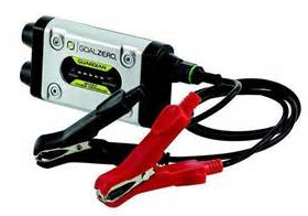
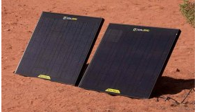
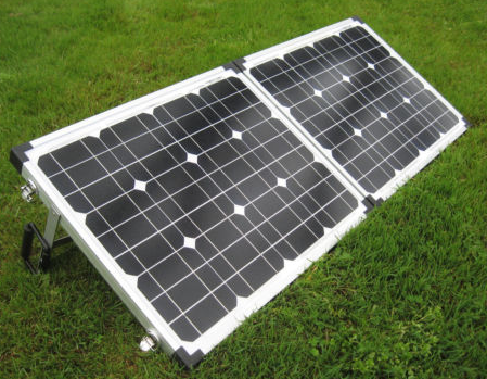
In that article I also laid out the different parts that would make up the “guts” of this project plus the two options of solar recharging. < click here to read Part #1 >

In this article I will go over step-by-step of this build. I hope that this gives you the motivation to consider a project such as this. It can be invaluable when you need your radio during emergencies, disasters or especially during a “grid-down” event. Let’s get started…

Step #1 – Securing the battery.

MiniMe-01It is of paramount importance that the battery be secured. Not that this is going to be rolled down a hill or placed upside down, but the battery shouldn’t move around too much. I also didn’t want to put a massive amount of weight or content inside the box either. On top of all of that, I wanted to make sure that it was relatively easy to swap out the battery. So therein lays the challenges.

So I kept looking at it trying to figure out what would be most MiniMe-02economical of material and weight. I had to secure it from moving up towards the lid and shifting lengthwise as well. First thing I did was secure one end of the battery that restricts its MiniMe-03movement towards the lid. I used a piece of 1-1/4” angle aluminum. I secure it to the box with pop rivets since this piece will not be removed from the box. Notice I used Gorilla Tape later to “pad” the piece of aluminum and to make it a bit more “sticky” helping to keep the battery from excessive movement.

Note #1: The pop rivets do not stick out further than the boxes hinge so I don’t see any problems with the pop rivets protruding a little bit.

Next I wanted to secure the whole length of the battery from moving towards the lid to prevent the battery from MiniMe-04
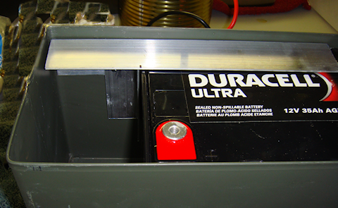
being damaged, and especially to protect it from shorting out across the terminals. That led me to the long support. But I still had the sliding lengthwise movement to be concerned about. And I wanted to make sure I didn’t restrict the volt meter installation. Once again, notice I used Gorilla MiniMe-05
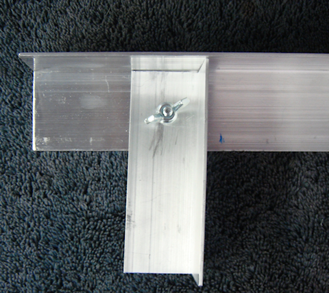
Tape to “pad” the piece of aluminum and to make it a pit more “sticky” helping to keep the battery from excessive movement.

I decided all that was needed was a single, albeit tall, piece of angle aluminum to keep it from sliding lengthwise. And then I realized I could attach it to the long support to minimize the number of holes through the box. And to top it off I would drill my volt meter installation hole through the 1-1/2” angle aluminum so I wouldn’t have to fabricate an instrument panel like I MiniMe-06
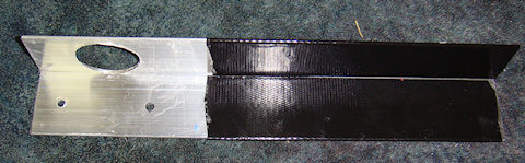
had originally intended.

I used Gorilla Tape to “pad” the piece of aluminum. Again, to make it a bit more “sticky” helping to keep the battery from excessive movement, but I also liked the more professional “look” it gave the overall fabrication.

The combination of the long horizontal retaining piece and the shorter vertical retaining piece are all held into place MiniMe-05by two #8 x 3/4” bolts. And those are secured with star washers and wingnuts. The wingnuts make it a whole lot easier to remove when, or if, it comes time to swap out the battery.

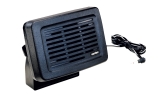
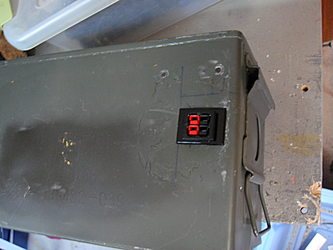
Step #2 – Installing the Powerwerx Panel Mount Digital Volt Meter.

I had originally was going to fabricate an instrument/control panel for inside the box. I was going to mount the volt meter to it and have  MiniMe-41
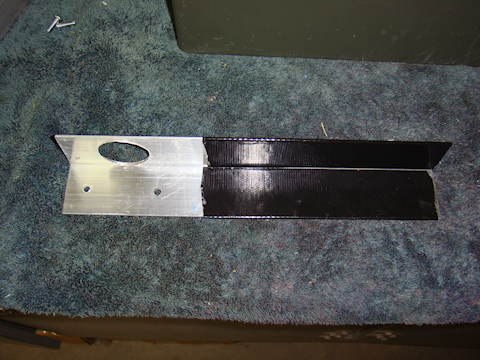
a little room left over in case I needed to install something else. But after looking at the set-up I had fabricated so far I decided to mount the volt meter directly to the long horizontal support piece (1-1/2″ angle aluminum). I used a 1-1/4” hole saw and had the hole done in a couple of minutes, filed MiniMe-40
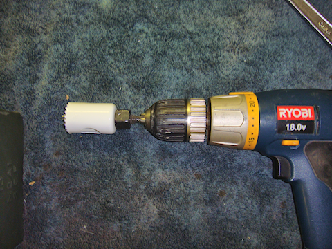
smoothed and Gorilla taped for looks but the tape also to help hold the volt meter in place.

Note #2: Make sure you leave enough room for the volt meter retaining washer that will fit on the back of the angle aluminum. If you get it to close to the angle itself then the washer won’t have enough room to fit.

Note #3: My hole saw had a real “wobble” to it. It is not the best quality hole saw, so you get what you pay for. I used the Gorilla Tape to clean up the hole and make it look more professional but I almost got the hole too close to the angle. I had to finesse it a little to get it tightened up. Measure the whole thing out really well before you start to drill the hole.

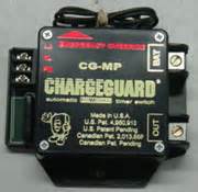
Step #3 -Installing the LVD (low voltage disconnect)

I had thought long and hard about installing an LVD in each radio box, but realized the proper location is the power box itself. I am using the Energy Core EC-LVD2. However, there is no temperature sensing by the LVD unit. So I will have to see how true to the voltage the cut-out point is. Also, I adjusted the “disconnect point” on the LVD to the highest setting it has to protect the battery, 12v. I did the adjustment outside in hot weather. Why? Because that is the most probable environmental condition that I will be operating the power pack in.

MiniMe-07
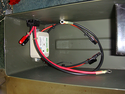
Next was to wire up the LVD with Anderson Powerpoles.The LVD only has a positive (red) wire to install in the circuit. The black wire is only to ground the unit itself. The heavy black wire you see in the picture to the left is simply to keep the whole wiring project organized and easy to understand.

I connected the black wire to the LVD’s red wire via zip ties. I didn’t have to. But this keeps the wiring straight and reduces the chances of confusion later if the box needs some electrical or wiring work done on it. Notice the small black wire by itself? That gets connected to the Red-Dee-2 block and grounds the LVD unit itself.MiniMe-08

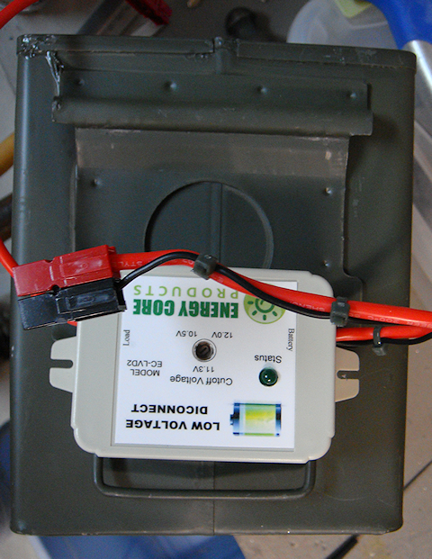
The next step was to properly place the LVD in the box. I placed it on the outside of the box to clearly see where it was to be installed and how it would look in relation to the entire installation. I marked, punched and drilled the holes based on the positioning on the outside. Verified that is fit on the inside that it was good to go. Perfect
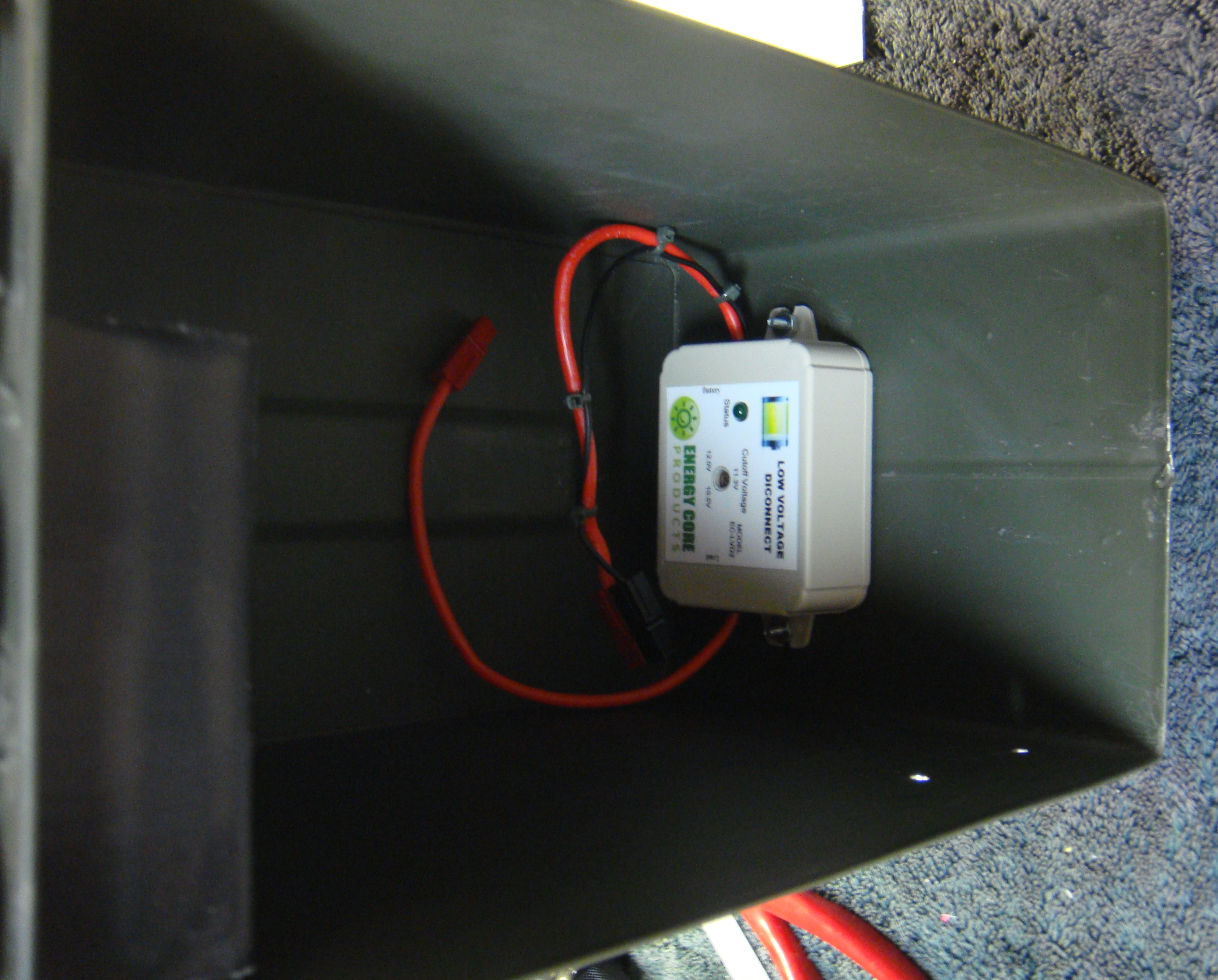
 MiniMe-09placement and fit.


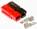
Step #4 – Installing the Anderson Powerpole Chassis Mount.Anderson Powerpole Chassis Mount for 2 Powerpoles Sets (4 conductors)

I am mounting the chassis mount on the opposite side from the volt meter to make sure I have enough room to get everything in the box without it being too jumbled up. The square hole that is required is slightly larger than 1″. I located the correct MiniMe-10position for the chassis mount to go through the box wall. I marked it really clearly, including the center of the square that was to be cut out.MiniMe-11

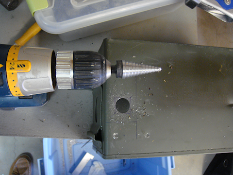
I have a 1″ metal hole saw that works really well through tougher metal and figured why not use that to remove the majority of the metal from the hole.

MiniMe-12
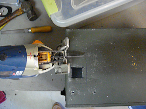
Once I had drilled out the majority of the hole I got out the saber saw with a good metal blade and squared off the hole easily. I used my flat file to clean up the edges.

MiniMe-13The chassis mount slipped into place exactly like it was designed to.


Step #5 – Wiring up the system.

Portable power box wiring diagramThe first step was to wire the chassis mount’s pre-installed Anderson Powerpole connections. I could have done a longer straight MiniMe-15run to the LVD connection. However, I am absolutely committed to MiniMe-14
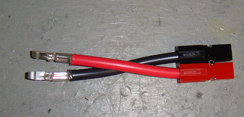
keeping everything modular and interchangeable. That being the case I used this short pair to connect the “power out” pair on the chassis mount to the Powerwerx Red-Dee-2 power splitter. See wiring diagram for more information.

The “power out” wires are wired to the top pair of the Powerwerx Red-Dee-2 for power box power distributionchassis mount. The lower pair in the chassis mount is for “power in” purposes. Those “power in” purposes? The solar charger, 12vDC direct charger, or to allow the power box to be hooked in parallel to its brother power box creating a 70 Ah power source.

MiniMe-42


I wired the “power in” wire pair directly to the battery with ring terminals and Anderson Powerpole connectors directly into the chassis mount. I wanted any “power in” to be connected directly to the battery to reduce current loss since it would be for charging the battery or running a parallel operation.

The wiring in pretty cramped and crammed in the box, but I was going for the smallest possible and practical box I could get everything into. It doesn’t have to look pretty, it just has to have quality parts and workmanship.  Oh, and it also has to work.MiniMe-50

Tip #1 – Notice I am using zip ties? That reduces the tension on the wires and takes the strain off the Powerpole connectors.

Step #6 – Testing the system

MiniMe-31
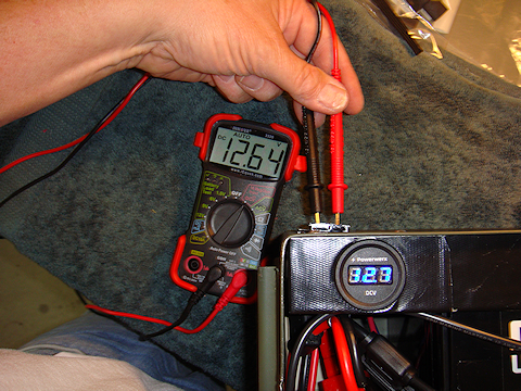
As always, before putting the power box into operation I had to test the entire system. I test it one component at a time as I hook each piece up. I get a volt reading directly from the battery that becomes my baseline. Then a reading through the ATC fuse connection. Then hook that to the Powerwerx Red-Dee-2 power splitter and test each outlet of the splitter.

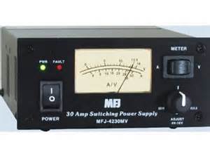
Then I hook up the volt meter and verify that it is getting the same reading my multimeter is getting. There was a .06 voltage difference. And that is only because the voltmeter only displays 10ths of a volt, whereas the multimeter displays in 100ths. Then finally I checked the connections in the chassis mount. All were good.

Step #7 – Protect the positive terminal.

There is a very minor issue that I felt I wanted to take proper precautions for. The positive terminal of the battery does not make contact with the box’s metal lid when the box is closed. But only by a small fraction of an inch. So I wanted to further reduce any chance of shorting the positive terminal to the box lid.

The way I did that was to cut two pieces of shrink wrap. One about 2″ long, the second slightly longer. I cut a notch out in the end of the first piece of shrink wrap to create a small “flap” that will cover the head of the bolt that is the positive terminal.

I then took the slightly longer piece of shrink wrap and did the same thing but made the notch larger to create a larger “flap” that covers more then just bolt head. So now I have two flaps of rubber that cover the head of the bolt that is the positive terminal of the battery. But I wanted to take it one step further. I took piece of my Gorilla Tape and ran it along the underside of the box. If the bolt head were to make contact with the lid, this is where ti would happen. So the layer of Gorilla Tape acts as an additional insulating layer.

MiniMe-23     MiniMe-22

bolt head battery terminal is covered with two layers of shrink wrap

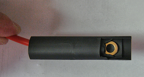
bolt head (battery terminal) is covered with two layers of shrink wrap


Final Product !

Looking at the box from the right rear corner

Looking at the box from the right rear corner


looking at the box from the left front corner

looking at the box from the left front corner

Final Note : Yes, I put the labels on there at an angle on purpose. It was a little flair, some dramatic license, to differentiate the purposes for the two sets of Anderson Powerpole connections.


2009 - 2019 Copyright © AHTrimble.com ~ All rights reserved
No reproduction or other use of this content 
without expressed written permission from AHTrimble.com
See Content Use Policy for more information.

Portable Power Box – Part #1

note: first appeared in July 2015

I am not a Ham radio “geek” but I do have a couple Ham radios and I like using them. One thing for certain, when an emergency, disaster, or “grid-down” strikes…radios will be essential. I mean “essential” not because they are a radio, but because communications will be absolutely necessary in those situations.

Along with the actual radio you have to have a quality antenna for your rig, that should go without saying. But what about power?


As with all my equipment I define a mission. The mission for this project is:

“Provide sufficient power to allow the limited use of a radio for at least 15% of any given 24-hour period. During which transmission power usage will be approximately 40% of that time period.”

Notice that the time period required to keep the radio operational is less than four hours of actual run-time. That may not sound like a lot but it could be significant when available power is at a premium. Stated in a little more “plain English” I want to be able to run my radio about 3.5 hours per day. And of that run-time I want to be able to transmit almost 1.5 hours. Based on the calculations stated in the mission, I need a 34 ampere hour capacity battery and the capability to recharge it.

And while I may have generator capability available to recharge the unit, I want it to be solar rechargeable. But, I don’t want it “tied” to a solar panel set-up. I want to be able to interchange whatever solar system I have or can come across to recharge the unit.

I also don’t want it overly complicated and not “multiple-mission” capable. This unit is strictly for powering a Ham radio and the ability to recharge it via generator or solar. Can it do other things? Of course. But those are side-benefits.

Here goes with the components –portable Power Box in a .50cal ammo can

For the storage box that will house everything I am going with a military surplus .50cal ammo can. It is a good size, very sturdy, and air/water tight. But most importantly it just seems to be the right size.

Once I picked out the box itself I was able to start looking into batteries. Obviously I wanted a “deep cycle” battery vs. a “cranking amps” battery. And the best/cost effective deep cycle batteries on the market right now are AGM style batteries in terms of how long they will keep a charge up. I won’t go into AGM details or why it is better; that’s way too technical for the scope of this article. That will be the focus of a later article just on that subject. But for now just know that I went with a deep cycle AGM battery. I wanted as many ampere hours as I could possibly get, but the box space was my limiting factor.

I spent probably 10 hours online looking at different battery manufacturers reading about the dimensions of different batteries and other details. I thought I had a battery identified correctly and ordered two. They arrived quickly, appeared to be solid, quality batteries. And of course, as you might guess, they didn’t fit.

I had rounded up the width measurement of the box, and the batteries had a very small lip on them that was not included in the technical information of the battery stating the actual width. Combine the two very small variances and the batteries would not fit side-by-side in the box I had planned. Fortunately, they were the same batteries that I had identified for another project so all was not lost. So, hours more searching online till I finally gave up. Good news is we have a Duracell Ultra battery 12v 35Ah AGM, model # DURA12-35CBatteriesPlus store in town so I grabbed the box and headed to the store. Ten minutes later I was walking out the door with a great battery, the Duracell Ultra 12v 35Ah AGM, model # DURA12-35C.

I was pleasantly surprised to have 35Ah capacity in such a small package. And remember that, based on my usage requirements, I needed a 34Ah battery or larger. You never know when the extra 3% capacity will be the one transmission you get out before the battery dies. Yeah, sorry a little melodramatic but you get my point.


So here are some technical facts on the DURA12-35C:

  • AGM technology (absorbed glass matt)
  • 12vDC SLA (Sealed Lead Acid) Battery Battery
  • 35Ah
  • U1 Group Size battery
  • Handles offer easy lift & carrying
  • Speedy connection with 6mm female threaded terminals
  • Size: 7-3/4″ L x 5-1/8″ W x 6-1/2″ H

Now here is a point of the box design that I struggled with just a little bit. I wanted to keep the integrity of the box intact. In other words I don’t want anything going through the box walls. That will keep it water and air tight. But I need to be able to have a set of Anderson Powerpoles to hook up a line to the radio and I need a set of Anderson Powerpoles to connect the solar charging unit to the box to keep the batteries charged up. And I want a voltmeter to keep track of the battery.

I have seen over the years that the more points you have that are vulnerable, the more likely you are to have a failure. So every breach of the boxes integrity is a potential failure point. But there is also the convenience factor as well; the box has to be easy to use.

Anderson Powerpole Chassis Mount for 2 Powerpoles Sets (4 conductors)This is where compromise and trade-offs come into play. I decided to go with the Anderson Powerpole Chassis Mount. This gives me a sturdy mounting system for two sets of Anderson Powerpole PowerWerx.com supplier of Anderson Powerpolesconnections (power out, charging in). The Anderson Powerpole Chassis Mount is available through Powerwerx.com

While the box is no longer water or air tight, I think it will fall into that category of “good enough.” While it won’t keep water out, it will resist rain. And while it isn’t airtight, it will keep most of the dirt and dust out. I am thinking that when I complete the install I will look for ways to seal it up on the inside to make it more resistant to rain and blowing dirt/sand.

To track the battery voltage condition I went with the Powerwerx Panel Mount Digital Volt Meter. It has a nice blue Powerwerx Panel Mount Digital Blue Volt Meter for 12/24V Systemsdisplay and I’ve used them before. Again, available through Powerwerx.com PowerWerx.com supplier of Anderson PowerpolesNice little high-quality units. But this volt meter will be mounted inside of the box not mounted on the exterior. To do that I would have to drill a 1-1/2” hole through the box sidewall and I am just not ready to make that size failure point.

I will have to fabricate a couple of “hold-downs” to keep the battery in-place. I will also have to fabricate a panel on which to mount the volt meter. I will integrate them just to make everything sturdier. And I will probably have to do a “bolt-through” or two to make it all stable. But I will try to keep those integrity breaches to a minimum.ATC Style Fuse Holder 10ga with 1/4" Ring Terminals and Anderson Powerpoles

To protect the electrical circuit I will use a Powerwerx ATC Style Fuse Holder 10ga with 1/4″ Ring Terminals and Anderson Powerpoles. The fuses are common, readily available and I can even pinch them from a vehicle if I need to.

There is a wildcard as far as interior components are concerned, LVD (low voltage disconnect). Overly discharging an AGM battery seriously reduces its life span (number of charging cycles). So you only want to draw it down to a certain voltage level. Based on the voltage stats of the Yaesu FT-8900R radio, the radio can operate down to about 10 volts before it shuts off. However, that is too much battery discharge under normal conditions for an AGM battery. Refer to the chart to see how the “depth of discharge” can serious reduce the number of times you can recharge the battery.

AGM battery discharge volts state of chargeAGM battery depth of discharge cycle chartNow, I can do one of two things to overcome that challenge:

1) Monitor the volt meter for a reasonable discharge depth, say 12.32 volts. And when the battery hits that level I manually turn off the radio till the battery is recharged.

2) Use a LVD unit that will automatically turn off the radio when a pre-set voltage level is reached. And it will also turn the power back on to the radio when it reaches a safe charge level once again. I am evaluating several different LVD units; one reasonably priced, the other is considerably more expensive. You can guess which one is probably better suited for this application. But I will provide more when my testing is done and I’ve made a final decision.

So that is it, no more guts for the power box than what I have outlined above other than the wiring. I will be using all Ham In The Box - Anderson Powerpole10g wire to ensure that the maximum current can be carried throughout the system. And, I want to make sure that I don’t overheat anything and burn it all up. As for connecting the wire to components I will once again be using Anderson Powerpole connectors for everything. This gives me a whole lot of options and flexibility. And most of all, when things get bad I can pull different pieces of my projects out to repair other more critical equipment. And I can do it with a minimal of effort, damage, and installation effort.

Solar Power –

I have already decided on two solar charging options:

Option #1 – A single panel system from GoalZero, Boulder 30 panel with the Guardian 12v charge controller. Goal Zero guardian 12v charge controllerThe charge controller has a built-in PWM Lead-Acid and supports up to 90W solar panels. It also has LED Status lights for the charging status and battery. Some technical specs on the panel –

Rated Power: 30WGoalZero Boulder 30
Open Circuit Voltage: 18-20V
Cell Type: Monocrystalline
Weight: 6.5 lbs
Dimensions: 21″ x 18″ x 1″
Optimal Operating Temp: 32-104 F
Certs: CE, FCC

Options #2 – A Glow Tech dual panel, portable system 60 watt folding solar kit, with folding stand, and integrated charge controller. Features of the Glow Tech system:

•   High efficiency monocrystalline solar panelsGlow Tech solar Power Box 60 watt folding solar kit, w/folding stand, charge controller
•   Suited for flooded, gel, AGM, or calcium batteries
•   Low iron tempered glass resists breakage
•   Durable folding frame, so you can tilt the panels toward the sun
•   Built-in PWM charge controller
•   Bonus! Includes fabric storage bag
•   Spring-loaded carrying handle
•   Solar panels are weatherproof and sealed to withstand the elements
•   Includes cables pre-wired for easy hookup
•   25 years warranty on the solar panels

Technical Info:

•   Rated Power Output:   60WGlow Tech solar Power Box 60 watt folding solar kit, w/folding stand, charge controller
•   Optimum Operating Voltage [Vmp]:   17.5V
•   Optimum Operating Current [Imp]:  3.43A
•   Open Circuit Voltage [Voc]:  21.7V
•   Short Circuit Current [Isc]:   3.82A
•   Normal Operating Cell Temp [NOCT]:  47±2°C
•   Maximum System Voltage:  1000 vDC
•   Series Fuse Rating:   10A
•   Operating Temperature:  -40°C to +85°C
•   Application Class:  Class A
•   Cell Technology:   Monocrystalline Silicon
•   Folded Dimensions (approx.):   22¼” x 17¾” x 3″
•   Unfolded Dimensions (approx.):  43″ x 18″
•   Total Weight (approx.):   19lb 7oz


2009 - 2019 Copyright © AHTrimble.com ~ All rights reserved
No reproduction or other use of this content 
without expressed written permission from AHTrimble.com
See Content Use Policy for more information.

Yaesu FT-8900r antenna stand and ground plane

Diamond CR8900A Quad-band antenna for a Yaesu FT-8900rnote: first appeared in March 2015

I have one of the best Ham radios on the market today, a Yaesu FT-8900r. It is a quad-band mobile radio that is simply the top of the line for its mission. To maximize its capabilities I purchased a Diamond CR8900A Quad-Band FM Mobile Antenna. I already have a NMO (New Motorola) mount on my truck’s roof. FYI – NMO is the defacto standard for professional antenna mounting. So, I have this really high quality radio, a matching high quality antenna and no real Yaesu FT-8900r Quad-Band Ham Radioway to use both in a ground-based application. Yes, I believe I am far more likely to use the radio outside of my truck during times of need.

So what antenna would I use?

The question is valid since the CR8900A requires a ground plane that is provided by the truck roof. A ground-based use would have no such metal roof as a ground plane. So I purchased a ground plane kit.

TRAM 1465 Land Mobile Base Ground Plane KitTRAM 1465 Land Mobile Base Ground Plane Kit. Cost was $22 through Amazon. The kit solved that issue but I was still undecided on how to set-up the antenna itself. So I went back to basics and defined the “mission” I was trying to accomplish.

Mission –

A highly portable and versatile quad-band antenna supporting my Yaesu FT-8900r which was capable of operating in almost any environment.

Solution –

Then it dawned on me, I had already built a support structure for dual UHF/VHF antennas that mounts to a camera tripod so why not do the same here. And so it was done.TRAM 1465 Land Mobile Base Ground Plane Kit

I put an additional bend in the bracket, drilled the appropriate sized hole in the “foot” of the bracket, and then went to Lowes to buy a wingnut to match the threaded post on the camera tripod. The camera tripod has a hook in between the legs in the center that I can attach a weight to hold the tripod steady to the ground. Because the tripod is adjustable I can have significant flexibility with the height of the antenna.

TRAM 1465 Land Mobile Base Ground Plane KitTotal time to build: less than 1 hour
Cost to build: Less than $25 (includes tripod bought at Goodwill)

Now when I set-up my Yaesu FT-8900r for ground based, non-vehicle, operations I have a great antenna stand to use complete with ground plane.


2009 - 2019 Copyright © AHTrimble.com ~ All rights reserved
No reproduction or other use of this content 
without expressed written permission from AHTrimble.com
See Content Use Policy for more information.

Yaesu FT-8900R Ham Radio : Storing and Case

Yaesu FT-8900r Quad-Band Ham Radionote: first appeared in March of 2015

In this post I will go over how I store my 8900R and what I store with it.

In two previous articles I went over the Yaesu FT-8900R radio and accessories. Both articles are worth the read:

Yaesu FT-8900R Ham Radio – Part #1
Yaesu FT-8900R Ham Radio – Part #2

So let’s go over my standard format, what is the mission for all of this?

Mission –

To safely store the radio and all components with which to operate the radio.

Requirements & Restrictions –
  1. Case must be sturdy, at least to military specifications.
  2. Case musty protect against dust, dirt, and water impingement.
  3. Case should protect the contents against damage due to reasonable heights and rough handling.
  4. Case should be low profile and not draw attention to them.
  5. Case should be light enough for one person to easily carry.

SKB i-series 3I-1711--68-C.The case I chose was the SKB i-series 3I-1711–68-C. These cases are waterproof and as sturdy, if not more so, that Pelican cases. And they are cheaper that Pelican cases. They come with “cubed” foam ready to be cut to size for your equipment.


SKB i-series 3I-1711--68-C for the Yaesu FT-8900R


So this is what my case looks like for my Yaesu FT-8900R.  The case is clearly labeled for easy identification.

SKB i-series 3I-1711--68-C for the Yaesu FT-8900RYaesu FT-8900R Radio Case –

Bottom Level:

  • 1 x Power supply, AC, 19amp
  • 1 x Mounting bracket, radio
  • 1 x Microphone, MH-48
  • 1 x Radio, Yaesu FT-8900R


SKB i-series 3I-1711--68-C for the Yaesu FT-8900RMiddle Level:

  • 1 x Power cord, AC


SKB i-series 3I-1711--68-C for the Yaesu FT-8900RTop Level:

  • 1 x 5′ Power extension cable, Anderson Power Poles on both ends
  • 3 x packages various mounting screws.
  • 1 x Mounting bracket, remote head
  • 1 x RT Systems Programming CD
  • 1 x RT Systems Programming cable
  • 1 x Power cable, Anderson Power Poles to hard soldier connection (AC power supply)
  • 1 x Cable, radio head to radio body
  • 2 x Fuses, 15amp

On top of the radio I place a 8900 user’s manual in a 1-gallon Ziplock bag with the latest copy of the US Amateur Radio Bands chart.

I have given you a list of the equipment needed to run the Yaesu FT-8900R Ham radio. Is it everything you might need?  This was meant strictly for the radio equipment itself and the essential equipment to get it going.

Take this list and use it as a starting point for your specific need and mission.


2009 - 2019 Copyright © AHTrimble.com ~ All rights reserved
No reproduction or other use of this content 
without expressed written permission from AHTrimble.com
See Content Use Policy for more information.

Yaesu FT-8900R Mobile Ham Radio – Part #2

Yaesu FT-8900r Quad-Band Ham Radionote: first appeared in February 2015

As mentioned in Part #1 of this series, I really love this mobile unit!  The Yaesu FT-8900r is an amazing piece of Ham radio technology wrapped up in a very compact and sturdy package.  This thing does it all and matches my mission requirements and then exceeds my expectations.

In the last post (Yaesu FT-8900R Mobile Ham Radio – Part #1) I covered the specifics of the Yaesu FT-8900R itself.  In this post I will go over the accessories, installation info and some other tidbits.


RadioAntennaCarVehicle external antenna for temporary dual band (2m & 70cm) operations : This antenna is a must have for temporary vehicle operations.  It is not a permanent antenna, it is a magnetic mount antenna.  You can move the antenna to other vehicles if needed.  You can also use it in a non-vehicle setting as well by placing the antenna higher than the radio would normally be located.  The drawback to this antenna is its design for dual-band operations (2m & 70cm) not all the bands that the 8900 is capable of using.  Great option where portability is needed and only dual-band operations are needed..

Diamond CR8900A Quad-band antenna for a Yaesu FT-8900r

Diamond CR8900A Quad-band antenna for a Yaesu FT-8900r

Diamond CR8900A

Vehicle permanent (or semi-permanent) mount external antenna : Diamond CR8900A Quad Band FM Mobile Antenna.  I love this antenna!  It took almost no tuning out of the box.  Probably really didn’t need to tune it all if truth be told.  The CR8900A is pretuned to give best bandwidth and VSWR over the FM portions of 10m, 6m, 2m, and 70cm Ham bands.  Designed specifically for the Yaesu FT8900.
Specifications:
Bands:        10m/6m/2m/70cm
Gain dBi:     2.15 (10m/6m/2m); 5.5 (70cm)
Watts:         60
Height:        50″
Connector:  UHF
Element Phasing:     1/4l-10/6; 1/2l-2m;2-5/8l-70cm

Note:  Not recommended for use with magnet mounts. Diamond CR8900A Quad-band antenna for a Yaesu FT-8900rGrounding required.  I would not run down the interstate at 75mph with this puppy mounted on your roof.  I feel this is a great antenna but better used when the vehicle is stationary.  It has a “fold-over” joint for storing when moving or going under low hanging branches…or through the McDonalds drive-thru.

Mobile Antenna Band    Frequency Coverage Range    Vertical Antenna Gain    Element Phasing (wavelength)
10 meters                              28-29.7 MHz                                2.1 dBi                                     1/4
6 meters                                50-54 MHz                                   2.1 dBi                                     1/4
2 meters                               144-148 MHz                                2.1 dBi                                     1/2
70 centimeters                     440-450 MHz                                5.5 dBi                                    2 x 5/8

Pull in the signals with Diamond Antenna CR8900A Quad-Band FM Mobile Antennas. Designed specifically for the Yaesu FT-8900 or FT-8900R radio, these antennas are pre-tuned to give the best SWR bandwidth over the FM portions of the 10m, 6m, 2m, and 70cm ham bands when mounted on the side of your vehicle. Plus, Diamond mobile antennas offer a “one-touch,” fold-over hinge that allows for easy access into low-overhead buildings.

Yaesu MLS100 external speakerExternal Speaker :  I had to go with a Yaesu MLS-100.  You can buy other speakers but I like the idea of a speaker that is matched to the radio by the manufacturer. The Yaesu Vertex MLS-100 external loudspeaker is a high performance communications speaker matching the impedance and output requirements of most Yaesu transceivers. It mounts on a swivel stand that is supplied along with mounting screws and bolts. A 6.5 foot (2m) audio cable that terminates in a 3.5 mm mono mini plug is also supplied. Black plastic cased speaker and black metal mount. Impedance is 4 ohms and the maximum power input is 12 watts. Yes, the FT-8900r has an internal speaker, but for vehicle operations and the associated noise I think an external speaker is really needed.  Dimensions: Height: 3.75 in., Width: 5.5 in., Depth 1.75 in.

Heil Sound - PMS-6 & Headset Adapter for YaesuHeadset with Boom Mic :  Heil Sound – PMS-6 & Headset Adapter.  Why?  Because I believe that there are times when you want, or need, more privacy or the ability to hear/speak under adverse conditions.  A headset with boom mic is the right answer.  The Pro Micro Single Side is a very unique high performance single sided headset.  This headset is outfitted with the HC-6 element and is designed for commercial broadcast applications, the -3dB points are fixed at 100 Hz and 12 kHz with sensitivity of -57 dB at 600 ohms output impedance (centered at 1 kHz.).  The microphone audio for the Pro Micro series terminates into a 1/8” male plug while the head phone terminates into a 1/8” stereo with adaptor. To adjust the headset simply bend the stainless steel piece that is inside the black padded headband.

Mic Gain
Adjust the mic gain while watching the ALC meter. Adjust so that the audio peaks just fill out the ALC scale and do not go beyond the ALC scale.

Speaker
The 706 speaker works all the time. To turn that off simply plug an empty 1/8” plug into the front headphone jack.

Vox  (voice activated transmission)
Set the Vox gain controls for proper activation.

Carrier Balance
If your rig has carrier balance it acts as a type of mic tone control. It is best to listen to yourself in another receiver as you transmit into a dummy load. You are actually moving the carrier + or – 200 Hz above or below the center of the filter network, which causes your microphone audio to change its tonal quality.  The use of the AD-1 series mic adapters allow simple interface with popular transceiver inputs. The adapter is 6” long and has a 1/8” female input jack for the boomset microphone and a 1/4” female that is for the PTT (push to talk) line for the Heil foot switch or hand switch. The 1/4” stereo plug goes into the headphone jack on the transceiver front panel.  All Heil Pro Micro Boomsets are shipped with foam windscreen that fits over the microphone. The windscreen does not change the frequency response, just the breath blasts directly into the microphone.

RT Systems ham radio programming softwareProgramming Software w/cable :  RT Systems FT-8900r Radio Software.  While the radio is fully programmable from the front panel that is not the way you want to try and program this radio. I tried several different “free” programming software program; had problems with all of them.  RT Systems puts out a superb product that can’t be beat in my opinion. FYI – You can use the files from any of the RT Systems software to transfer to any other radio that you are programming.  So I can use all programming I did for my FT-60r for my Yaesu 8900 radio with a simple click of a software button.


NOTE: I will be posting programming files for different parts of the country as well as different repeater systems.

MFJ-4230MV COMPACT SWITCHAC Power Supply : MFJ Enterprises Inc. MFJ-4230MV COMPACT SWITCH (COMPACT SWITCH PS, METER, 4-16V ADJ. 110/220VAC).  This is a great AC power transformer, high quality and very reliable.

This is the world’s most compact switching power supply that also has a meter and adjustable voltage control. Just 5″ W x 2 ½” H x 6″ D, it weighs only 3 lbs. — it is the perfect pack-n-go power supply for field day, DXpeditions, camping, hiking or to pack for your next business trip or vacation to some far away place. MFJ-4230MV gives you 25 Amps continuously or 30 Amps surge at 13.8 VDC. The voltage is front-panel adjustable from 4 to 16 Volts. MFJ-4230MV also has a selectable input voltage: choose from 120 or 240 VAC at 47 – 63 Hz.

A simple front-panel push-button switch lets you choose either Ampmeter or Voltmeter — allows you to select Amps or Volts as you wish to read them. MFJ-4230MV has an excellent 75% efficiency and extra low ripple and noise, < 100 mV. Awhisper-quiet fan cools by convection and forced air cooling. Normal air-flow around the power supply is continuous and a heat sensor increases the fan speed when the temperature rises above 70 degrees Celsius. DC output is five way binding posts on the back of the MFJ-4230MV so you can power your dedicated HF, VHF or UHF transceiver with ease.

Charge Guard CG-MP

TIP – Battery protection when installed in a vehicle :  I also use Charge Guard CG-MP timer for my truck’s power installation.  This ensures that I won’t inadvertently run my battery dead using my Ham radio without the engine running.  Well worth the $’s.


Anderson Power PolesTIP – Power connectors :  I use Anderson Power Poles for all my power connections.  This makes hooking up my power “brainless” and quick.  Plus it gives me the added advantage of using power cables, fuses, etc. for more than one radio.  Basically allows for flexibility.  I chose Anderson Power Poles because there are essentially the standard for Ham radio operators.


So this concludes my review of the Yaesu FT-8900r quad-band radio.  It is a solid “Buy!”  You will not be disappointed and it will serve you for a very long time.

2009 - 2019 Copyright © AHTrimble.com ~ All rights reserved
No reproduction or other use of this content 
without expressed written permission from AHTrimble.com
See Content Use Policy for more information.

Yaesu FT-8900R Mobile Ham Radio – Part #1

Yaesu FT-8900r Quad-Band Ham Radionote: first appeared in January 2015.

I really love this mobile unit!  The Yaesu FT-8900r is an amazing piece of Ham radio technology wrapped up in a very compact and sturdy package.  But before I gush all over this little beauty let me get into some of the nuts and bolts of what makes this mobile unit fit my need.

Right after getting my Ham Radio License I was looking to buy my first radio.  But before just running out and buying the first radio that I could find, I wanted to describe exactly what the mission was and any specific requirements I might have for a Ham radio.  If you do it and you do it right, that may take a little time because you have to think through scenarios, set priorities and use both common sense and analytical skills.  So here goes…

Mission –

Provide reliable clear communications over the widest range of radio frequencies for both normal daily operations and emergency/disaster/”grid-down” situation.

Requirements & Limitations –
  1. Must be sturdy, reliable and able to function in harsh environments; including in a off-road truck.
  2. Must be able to run on 12vDC power.
  3. Must have an internal speaker and have external speaker capability.
  4. Must be intuitive to operate from the front panel.
  5. Must be easily computer programmable.
  6. Must be able to scan all frequencies in all resident frequency bands.
  7. Should have a a large number of memory channels (at least 200).
  8. Should be able to dual scan all frequencies in all resident frequency bands.
  9. Should move easily from home to vehicle to field operations without undue effort.
The Good & Less GoodYaesu FT-8900r Quad-Band Ham Radio

I had previously purchased a Yaesu FT-60r handheld radio and was very impressed with its obvious quality and reliability.  It is a very sturdy unit that has a lot of built-in capabilities.  Read more about the Yaesu handheld FT-60r radio.  While I did search all available brands I was predisposed to being partial to Yaesu based on my experience with the FT-60.  I did the typical side-by-side comparison of unit capabilities and performance.  It soon became very obvious to me the 8900 was the right mobile radio for me.

Here are some of my findings:

  • The keys located on the microphone are fully programmable for all your common usage.  So you don’t have to use the buttons on the radio head while driving.  Simply hold the mic and hit the appropriate key.  Examples: scan stop/start, change bands, volume control, etc.
  • You can use this radio as a “cross-band” repeater.  And that my friends is an amazing option to increase the

    Yaesu FT-8900r Quad-Band Ham Radio

    Remote head installation.

    distance of your teams’ handheld radios.

  • Ability to monitor or scan two bands simultaneously.
  • With the remote head you can mount the main radio body in a safe secure location.  The mount the small lightweight head wherever it makes the most sense for you and your vehicle.
  • Runs cooler than other rigs I have seen or heard about.
  • 50 watts of power enables this to be used as a great base station as well as a mobile.

There are some minor, very minor, drawbacks:

  • The buttons are not back lit.  I actually like this for OpSec purposes in a way.
  • The knobs on the front panel are a little on the flimsy side.  But I am not abusive on my radios so I am not worried about that.
  • You really need a computer and software to program this radio.  There are many features and trying to program them, or the frequencies, is more than difficult for me without the software.

This radio is four band capable and that is exactly what I was looking for and exactly what I got.  This is a great radio!

The Details

The FT-8900R is a ruggedly-built, high quality Quad Band FM transceiver providing 50 Watts of power output on the 29/50/144 MHz Amateur bands, and 35 Watts on the 430 MHz band. It includes leading-edge features like cross-band repeat, dual receive, VHF-UHF Full Duplex capability, and over 800 memory channels. And its 10-meter FM coverage brings the possibility of world-wide FM DX-ing to you on your drive in to work!Yaesu FT-8900r Quad-Band Ham Radio

  • Transmits 50 watts on 10, 6 and 2M, & 35 watts on 440 MHz, With Selectable Lower Output Settings.
  • Receives (less cellular) 28-29.7, 50-54, 108-180, 320-480 and 700-985 MHz, Transmits 28-29.70Mhz, 50-54Mhx, 144-148Mhz, 430-450Mhz.
  • Backlit Keypad mic, 800 mem Channels, Live Dual Displays, ctcss/dcs (PL & DPL).
  • Features Cross Band Repeater mode, 1200/9600 bps Packet Jack, AlphaNumeric Display, V/V, U/U, V/U.
  • QuadBand Amateur Ham Radio FM Mobile Transceiver.
  • 10 Meter, 6 Meter, 2 Meter & 70cm Transmit.
  • Full Cross Band Repeat.
  • Remoteable Faceplate
  • Full Duplex operation.
  • Requires Optional suitable Antenna(s), & Hookup to 12-14vDC at least 12 Amps.
  • Convenient Remote-Head Mounting Capability
  • Convenient Access to WIRES and other Internet-linking Systems
  • Quad Band Operation
  • Wide Frequency CoverageYaesu FT-8900r Quad-Band Ham Radio
  • High Power Output
  • Over 800 Memory Channels
  • Cross-Band Repeat Capability
  • One-Touch Band-Pattern
  • CTCSS and DCS Encoders Built In
  • Easy Setup for FM Satellite Operation
  • Truly Independent Two-Channel Operation

Wide Frequency Coverage

The FT-8900R provides extended receiver coverage beyond the Amateur bands, so you can keep informed of communication activities in the public safety, commercial, aircraft, and government communications ranges.

Independent Two-Channel Operation

The FT-8900R operates as two radios in one simultaneously monitoring the two bands. Each band has its own Volume and Squelch controls.

High Power Output

To get your message through when it counts, the FT-8900R puts out a full 50 watts on 10, 6 and 2M, & 35 watts on 440 MHz. There are optional lower output settings.. A thermal sensor monitors heat sink temperature, engaging the rear panel’s cooling fan only when needed.

Over 1000 Memory Channels

The FT-8900R provides a wide variety of memory resources, including 512 “regular” memories on each band, five “Home” channels for favorite frequencies, ten sets of band-edge memories on each band, and six “Hyper Memories” that store complete sets of transceiver operating status configuration.

Large, Easy-to-Read Liquid Crystal Display (LCD)

Affording easy viewing from a wide range of viewing angles, the LCD of the FT-8900R features Yaesu’s renowned Omni-Glow™ display illumination, with four illumination levels available for different environments. You’ll marvel at the crystal-clear frequency display and status indicators, whether you’re operating night or day!

Cross-Band Repeat Capability

For emergency work, or to extend the range of a hand-held dual-band unit, the FT-8900R includes Cross-Band Repeat capability, similar to that pioneered on our popular FT-8100R Dual Band FM Mobile!

One-Touch Band-Pattern

To save valuable time while operating a transceiver with the capability of the FT-8900R, the “Hyper Memory” feature allows you to store a complete set of configuration data for the two bands on which you’re operating. Besides the usual storage of frequency and tone data, Hyper Memory will store such setup parameters as Automatic Repeater Shift status, Packet parameters, Scanning mode, and VFO tracking configuration.

50-Tone CTCSS/104-Tone DCS (Digital Code Squelch) Tone Systems

Providing excellent performance even under difficult link conditions, Yaesu’s 50-tone sub-audible CTCSS and 104-tone DCS signaling systems ensure that you have full access to repeater and remote-base inputs, and the built-in CTCSS/DCS decoders allow silent listening on busy channels. Plus you get Tone Search Scanning, which will scan for the tone being received on an incoming signal, allowing you to match tones quickly when operating on a new repeater system.

User-Programmable Microphone Keys

Four programmable keys on the microphone allow you one-touch access to your favorite command functions. The commands available from the microphone replicate the corresponding front panel key functions, and include Band Change, VFO/Memory switching, Home Channel access, 1 MHz frequency steps, Power Output selection, Repeater Reverse, and CTCSS/DCS setup. Customize your microphone for your personal operating style!

Convenient Remote-Head Mounting Capability

With the FT-8900R and its optional YSK-8900 Separation Kit, mounting your radio is a breeze even in the tightest locations. The YSK-8900 includes a 20-foot (6 m) remote cable and mounting bracket for the front panel.

This is a “BUY!”


2009 - 2019 Copyright © AHTrimble.com ~ All rights reserved
No reproduction or other use of this content 
without expressed written permission from AHTrimble.com
See Content Use Policy for more information.