note: first appeared late 2015
In the first article published about 30 minutes ago I described what I was trying to accomplish and then I defined the specific mission. Once all that was done I was able to list the individual components that would go into the box and the specifics for each.
This article will give you a step-by-step description of exactly how I built the final rig. I have even included some notes with pointers and suggestions.
I really hope this shows you how simple this stuff can be. And I also hope it motivates you to get some decent communications gear and capability ready for emergencies, disasters and grid-down.
Let’s get on with it…
The Build
My main concern was the limited space and heat generation. I wasn’t worried about the battery orientation because it is a sealed battery and won’t (shouldn’t) leak. Since the box will spend most of its life sitting upright in storage like a normal ammo can, I decided to orient the battery installation to be upright when the ammo box was in its normal upright position. When the radio unit is operational the ammo box will be sitting on its side and so will the battery. That shouldn’t pose any problem at all.
But, exactly how to secure the battery so it wouldn’t move around was the single biggest challenge. Before I tackled that issue I did have to get the radio positioned, but that proved to be really easy. It would be oriented vertically when in operation, horizontally when stored. Also, this would call for a remote head installation.
Step #1 – The Radio.
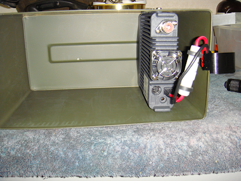
No matter how I looked at it I could only see one reasonable way to mount the radio, and that would require four holes drilled through the box to properly secure the radio. I also wanted to leave a little room so the remote head extension cable can be connected without rubbing against the bottom of the metal box. To protect the cable, the radio will sit 1/2” off the bottom of the ammo box.
I also wanted to mount the radio so the speaker orientation was facing up, directly toward the box side, so the sound would bounce off the box giving the volume a little boost. That would place the built in fan pointing out helping with air  flow. The fan starts up when a transmission is initiated.
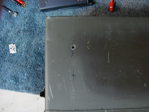
I made measurements approximating where the first radio body hole would be drilled through the box. I used my square to keep all the measurements exact and consistent. I laid out the first hole, punched the starter “dent” and drilled the hole. I was using the standard Yaesu installation screws so I sized the hole appropriately; the mounting screw barely went through the hole.
Once I drilled the first hole I tested the hole in relation to the radio and it was a good match. The radio would end up exactly where I wanted it inside the box.
Once that was done I then used the measurement between holes on the radio to verify the earlier mark for the second hole on the same side of the box. I punched the starter “dent” and drilled the hole.

Couple notes…
Note #1 – I used a really good “punch” to start the hole I would drill. If you don’t punch a starter dent your drill bit will tend to “walk around” and your measurements go right out the window.
Note #2 – I marked an “X” across each hole in the radio. It would  make lining them up easier once the radio was inside the box. You can see each “X” through the hole in the box as it passes by.
Note #3 – I have a really decent little set of diamond files. I bought them at Harbor Freight. They were only a few bucks and I have used them more than any other set of files I have. I use the little rat-tail file to clean up the inside of the drilled holes.
Note #4 – After you have drilled each hole you need to follow Note #3. Once that is done use a flat file for ammo box metal and clean up the inside of the box where the hole went through the side of the box. There will be sharp jagged edges unless you file them flush with the box.
Note #5 – After I drill each hole I test it for alignment with the radio chassis. I actually install the mounting screw but only part way. Only “part way” allows for some wiggle room when testing the other holes’ alignment.
Both holes on side one lined up perfectly. I took the radio back out and then measured the holes’ placement with the square. If, on the other side of the box, I use these measurements exactly then they should line up perfectly. Notice how I measured in from the sides and bottom and top (3-way) measurements to ensure proper placement of the new holes.
Next came measuring and drilling the opposite side of the box for the mounting holes. I measured from the top, bottom and end using my square. Transferring the measurements from the other side should place these holes in the correct location. I punched the starter dent for hole #3, drilled it, cleaned it up, tested the alignment and bingo! It came out exactly right. Then on to hole #4. I verified the measurement against hole #3 to verify that it would be right. It came out with a slightly different placement, i made the adjust and went on.
I punched the starter dent for hole #4, drilled it, cleaned it up, tested the alignment and bingo! It came out slightly off. I got out the rat-tail diamond file and enlarged it slightly correcting the alignment. I was off by less that the depth of the screw’s thread. I had it corrected in less than a minute of filing. That diamond file is really sweet.
I then tested the alignment with all four mounting screws and it came out right on the money.
Step #2 – The Battery.
Next I had to resolve the issue of securing the battery, this was going to be no easy task. I spent a whole bunch of time looking at different mounting options. Finally I came up with something I thought would work well.
I knew that no matter what, I had to secure one end of the battery really well. So I put the permanent mounting bracket in the most natural spot that I could, the hinge end of the ammo can. Then it seemed only right that I put a piece of angle aluminum across the whole end to secure the battery no matter its exact side-to-side alignment.
I placed the battery in the can and measured from the top of the ammo box to the top of the battery and I drew a line on the metal can across the top of the battery on the end of the ammo box metal. I double measured the line from the top of the box. I added a very small additional space allotment during this process. The thickness of Gorilla Tape to be exact. Once this was done I transferred that line to the outside of the ammo can.
Note #6 – I decided to use pop-rivets to secure this bracket to the back of the ammo can. I didn’t see myself ever needing to take this piece off so I decided that riveting it would be just fine.
I drilled my first hole through the angle aluminum 1″ from the first side. I would do the same on the other side of the aluminum angle as  well. I lined up the angle aluminum piece, now with the holes in it, and marked my first hole on the ammo can. I “punched” it, drilled, and cleaned up that hole. I placed the angle bracket piece on the can lining it up with the newly drilled hole and the drawn alignment line. I placed a rivet in the hole to stabilize it and give me a sure spot for hole #2. It did and I marked hole #2 on the ammo can. I “punched” it, drilled, and cleaned up that hole.
I moved the securing angle aluminum bracket to the inside of the box, verified the hole alignment and riveted it in-place. I placed the rivet on the inside of the can, pushed it through the box placed a  rivet washer on it and finished the riveting process.
Note #7 – I used rivet washers to make sure I had a good strong fit of the bracket to the ammo can. The washer goes on the outside of the box over the end of the rivet prior to finishing the riveting process.
I finished it off with two layers of Gorilla Tape to protect contact with  the battery case. I inserted the battery and everything fit snug. Just like it was supposed to.
Now it was time to figure out the next step in securing the battery. But after about an hour of looking it over I gave up. Well, I should say I took a break to give my mind a rest and pray for a new idea or two.
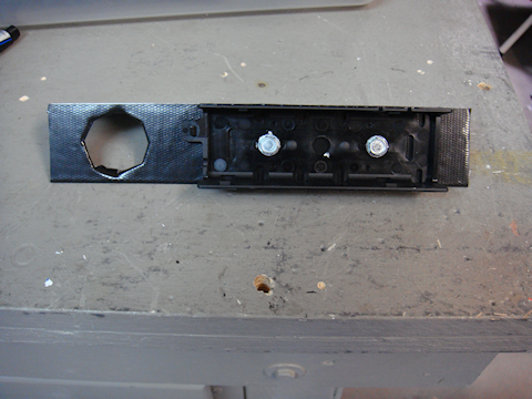
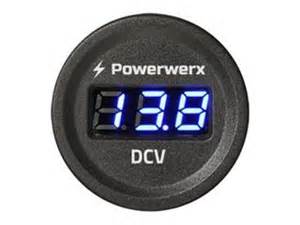
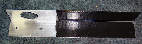
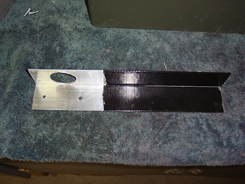
In the meantime I figured I could go ahead and fabricate the bracket that would hold the remote radio head bracket and the volt meter. I took an 8″ long piece of 1-1/2″ angle aluminum, laid out the location for the volt meter hole first, then ensured that the remote head bracket would leave enough space from radio chassis. I decide that I wanted the remote head in the center of the box to give it the most protection from damage. Also, I wanted it shaded the most from the sun and other light as well. So the volt meter would get mounted on the end of the bracket closest to  the hinged end of the ammo can.
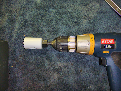
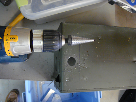
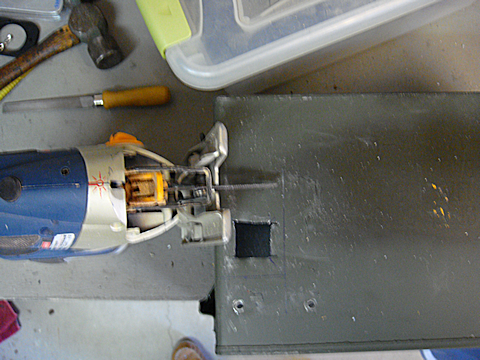
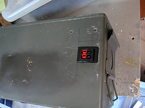
I used 1-1/2″ sock to give me enough room for the 1-1/4″ hole I would have to drill for the volt meter. Now, let me tell you right up front…use a good quality hole saw. If you use a cheap hole saw you may get  enough “wiggle” or “wobble” in the hole saw that your hole ends up too large. My old one was shot so I went out and bought a Lennox Bi-Metal hole saws and I am real happy with them.
Once the hole for the volt meter was cut, I Gorilla taped the face of the bracket and tech crewed the remote head bracket into place. Yes, the hammer is there to make the “fine” adjustments that might be needed 😉
I attached this mounting bracket to the side of the ammo can using the previously installed hinge-side battery bracket to hold it in place. While I was lining up the bracket to drill another hole in the ammo can to secure it, I “saw” the solution to finish securing the battery in-place. It is hard to describe to you so let me just show you the pictures.

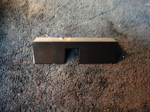
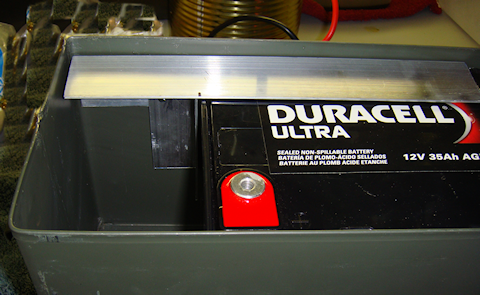
 I cut a 4-1/2″ piece of 1-1/2″ angle aluminum to it would fall just shy of the positive terminal of the battery by about 3/4″ of an inch. Then I cut a notch to match where the negative terminal sits on the battery. I Gorilla taped it to protect the battery case from the edges between the battery and the aluminum.
Now I just had to figure out the last little question of keeping the battery from moving side-to-side.
The answer was to drill a hole and place a bolt through the angle aluminum. I didn’t want the battery case exposed  to the bolts threads so I installed nuts on the bolt. I topped it off with a lock-nut at the end. Then I put two layers of heat shrink over the nuts.
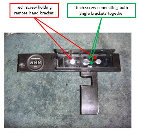
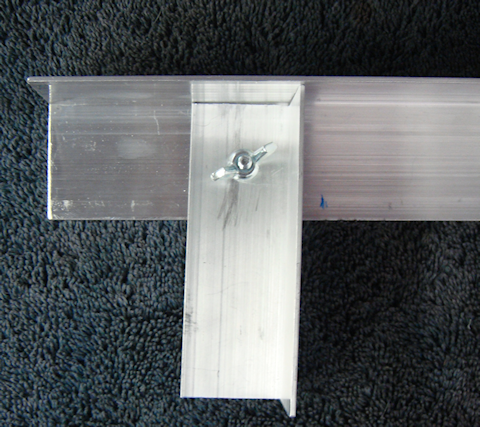
Then I figured out how to permanently attach that bracket to the 8″  piece holding the remote head bracket and the volt meter. I used a large tech screw in the center of the remote head bracket and a smaller tech screw to the bottom right of the large one. In the picture to the right the “large tech screw” is the one in the middle of the remote head bracket. In the picture to the right – red are the tech screws that hold the remote head bracket is held to the angle aluminum, green are the tech screws that hold the two pieces of angle aluminum together.
I installed the volt meter and tested for fit and alignment. Ooppppsss!
I hadn’t accounted for the volt meter protruding through the bracket, it ran square into the riveted bracket that is holding the battery in-place. So I had to drill out the rivets and notch that battery hold-down bracket to make room for the volt meter.  Time…10 minutes and I was back in operation with a perfect fit.
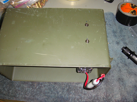
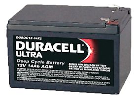
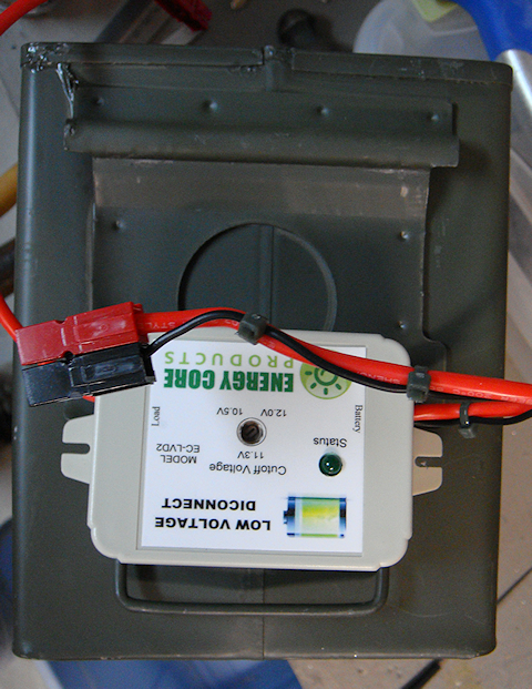
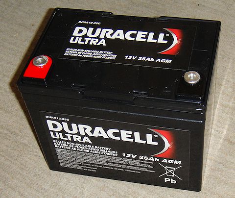
Now it was time to start wiring some stuff. First up was my battery  connections. The battery has “F” style terminals. The right piece of equipment to make this happen is a Powerwerx ATC Style Fuse Holders with F-Type Connectors and Powerpoles to make the connection.
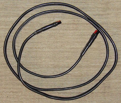
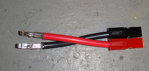
——-Side note – But I wanted to be creative and challenge myself a little. I wanted to “adapt” something to see what I could come up with.  I had a Powerwerx ATC Style Fuse Holder connector with Powerpoles on both ends siting in my electronics kit. I figured I would just cut off the Powerpoles on one end and put a couple “F” connectors on the ends. But then I started thinking, would that match my “flexibility” intent? Nope! So I made a converter. I put “F” type connectors on one end and Powerpoles on the other end. Now I would hook that up to the battery and then plug the fuse holder connector onto
  the converter.
But I would would have bare metal connectors on the battery terminals and that is a recipe for disaster…spark, sizzle & smoke.
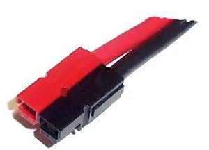
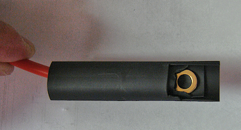
 So I got out some 5/8″ shrink wrap, cut to size, and heated that stuff up to form my own protected “F” style connectors. Yes, I did it to both connectors. I just wanted to show you a before and after picture.
Note #8 – Notice the zip-tie on the wire? That it sued to keep the tension off the Anderson Powerpole connector. The zip-tie stabilizes  the wire to each other taking the tension off the Powerpoles.
Bingo! Adapt and overcome! used what I had on hand to make it happen while not destroying an existing resource. Wow! That sounds like the #3 rule of L.I.P.S. “Don’t destroy anything you don’t have to.”
——-End of side note——-
Once I had completed that exercise in creativity I installed the pre-made “F” type ATC fuse connector that I purchased from Powerwerx.
Tip – When you remove the terminal protectors from the new battery…save them. Put them in a little plastic bag and place them in your electronics kit. You never know when  you might need to put them back on the terminals for protection when the ATC connectors have been removed.
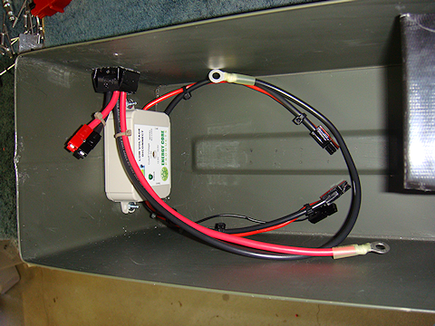
I fabricated the wiring to connect the volt meter to the power distribution hub. For this “build” I am using a Powerwerx Red-Dee-2 (old style) 4-way power distributor.
Notice there is no power switch. To remove power from everything you disconnect the ATC fused line from the Red-Dee-2 power distributor.
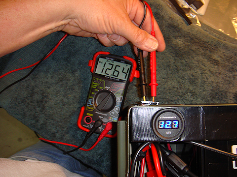
I went through my standard “start-up test” procedure –
- Test the battery with the multimeter first. That gives me a baseline reading.
 Hook-up the fused connector, test with multimeter.
- Hook-up the 4-way power distribution Popwerwerx Red-Dee-2, test each outlet with multimeter.
- Hook-up the volt meter, test with multimeter.
- Hook-up the radio after checking it’s dedicated fuse. Test with multimeter before turning on the radio.
- Turn on the radio and pray there is no sizzle, sparks & smoke!
It all turned out really well. There was a .04v variance between the volt meter and the multimeter but the volt meter rounds to the nearest 1/10th volt. So it was all good. Yes, I hooked up an antenna before I turned on the radio.

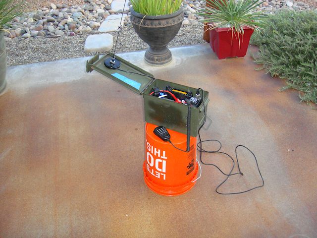
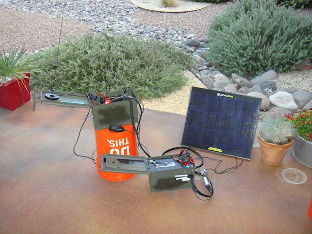
Next came the field test. Everything worked as designed, as built and as tested. Yea!!!!

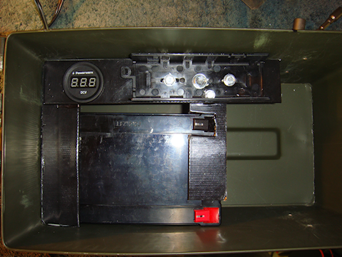
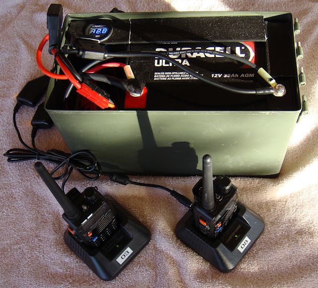
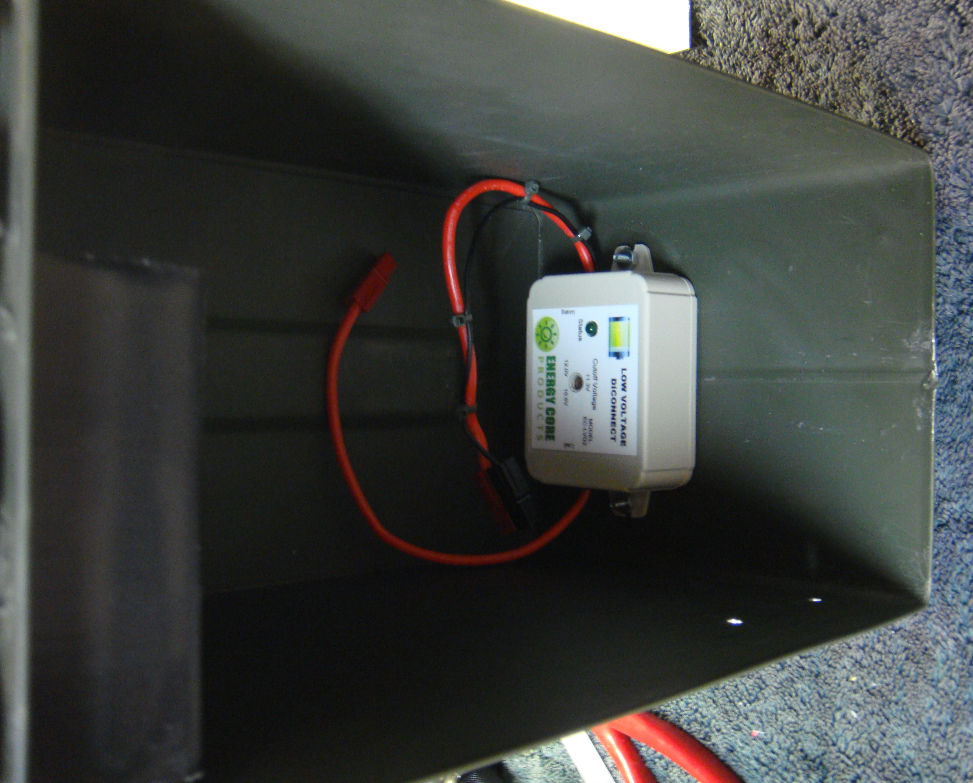
Looking down into the box.

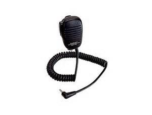
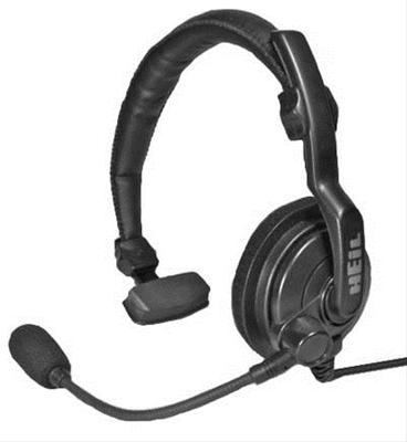
Microphone gets stored in padded envelope. Protects the mic and cushions everything else.

View #1 – from front-right corner of the secured ammo can.

View #2 – from rear-left corner of the secured ammo can.
The weight of the box came in at a total of 19 pounds, that is everything, including the battery. This came out to a very compact radio “go-box” that can be taken anywhere. You can also just throw it in a backpack and head up the mountain.
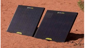
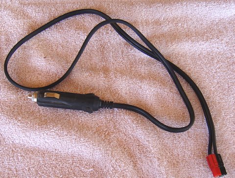
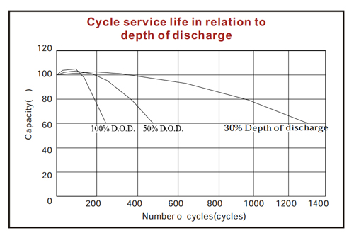
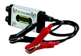
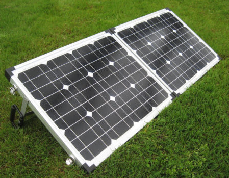
The solar recharging capability is a serious bonus. This gives you a renewable energy source that you don’t have to scrounge up or steal from something else like gas for a generator.
Remember…this was built for a Yeasu FT-8900R. But a Yeasu FT-8800R also fits it. Both of those radios have built-in cross-band repeater feature. You open up, the box, plug in the solar, turn it on, set-up the frequency package and you are ready to operate. You are in business if you use it as a regular Ham radio for communications or let it run remotely as a repeater.
I hope you enjoyed reading about this “build” as much as I enjoyed making it. But I sure would like you to take this information and put it to use meeting your own radio needs. If you have any questions or need help with your build just “reply” here let’s tart talking.
2009 - 2019 Copyright © AHTrimble.com ~ All rights reserved
No reproduction or other use of this content
without expressed written permission from AHTrimble.com
See Content Use Policy for more information.

 note: article first appeared in January 2015
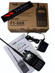
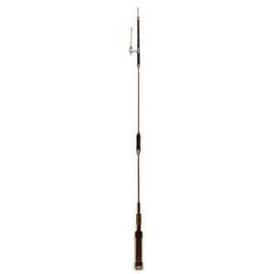
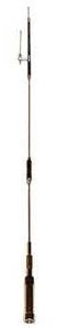
 Comet SMA24 DualBand Amateur Radio & Scanner SMA Antenna For Handhelds – 2M/440
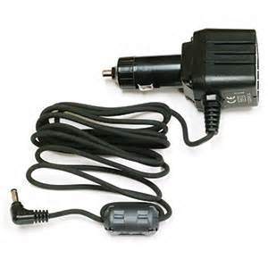
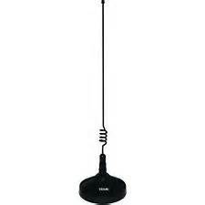
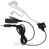
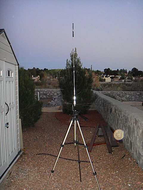
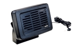
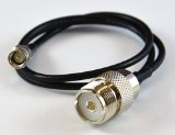 Vehicle external antenna & Connector cable plus speaker/microphone : This three-part accessory is a must have for vehicle operations. Operating a handheld radio inside your vehicle will reduce its power to reach out longer distances due to the metal shell of your vehicle. It may also interfere with the quality of transmission as well; making your message sound distorted at the other end. You overcome this by mounting an antenna on the roof of your vehicle. Not a permanent antenna, a magnetic mount antenna; you can move the antenna to other vehicles if needed. You can also use it in a non-vehicle setting as well by placing the antenna higher than the radio would normally be located. You must use the adapter cable to connect the radio to the antenna cable. Using the separate speaker/mic prevents wearing out the connection between the adapter cable and the radio. You don’t have to hold the radio and move it around, you simply use the speaker/mic and leave teh radio sitting in one place.