The Victron Lynx Distribution System is a modular busbar system that incorporates DC connections, distribution, fusing, battery monitoring and Lithium battery management.
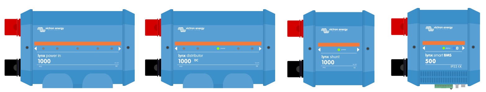
The system consists of the following components:
- Lynx PowerIn
- Lynx Distributor
- Lynx Shun
- Lynx Smart BMS
 Each component’s main part is its 1000amp positive and negative busbars. And each component’s primary feature is the ability to connect together via the 1000amp busbars. However, each component has a separate function, they are:
- Lynx Smart BMS – Only for use together with Victron Energy Smart Lithium batteries. If you don’t have Victron batteries, then you won’t ever need this component.
- Lynx Shunt – Operates much like a smart shunt to monitor system energy usage. It connects to a Victron GX device to display that information, and the information can also be accessed via the VictronConnect app.
- Lynx Distributor – Along with positive and negative busbars, there are 4 fused connections for batteries or DC equipment together with fuse monitoring.
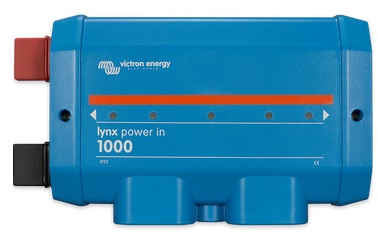
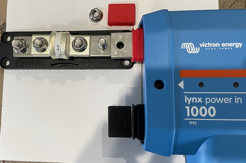
- Lynx PowerIn – Is essentially a Lynx Distributor without the computer board, fuse holders, and monitoring.
 And the PowerIn component is the subject of this post. Why? Because I love it and I am using it in my upgraded glamstead solar power system. And most of all…you might find it useful as well!
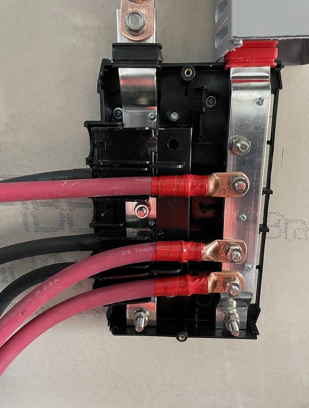
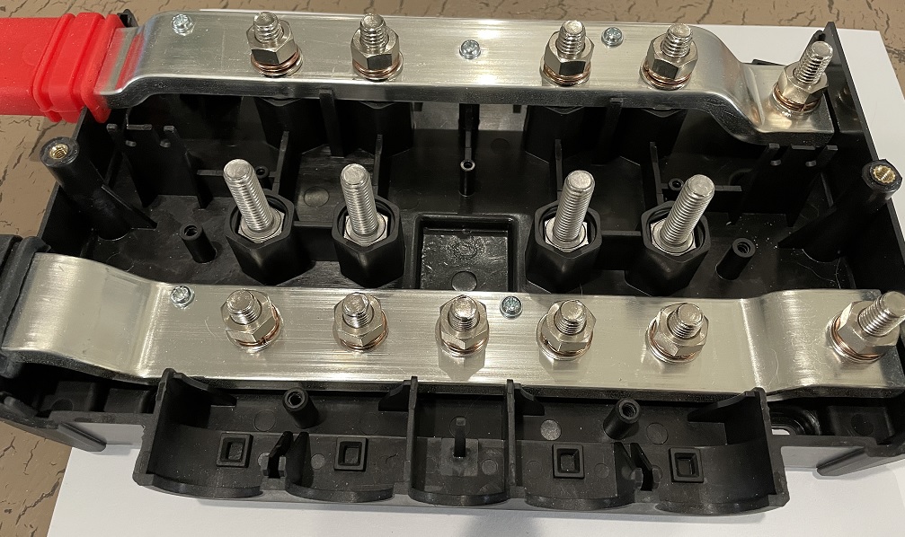
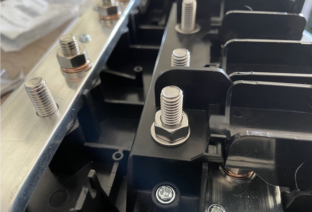
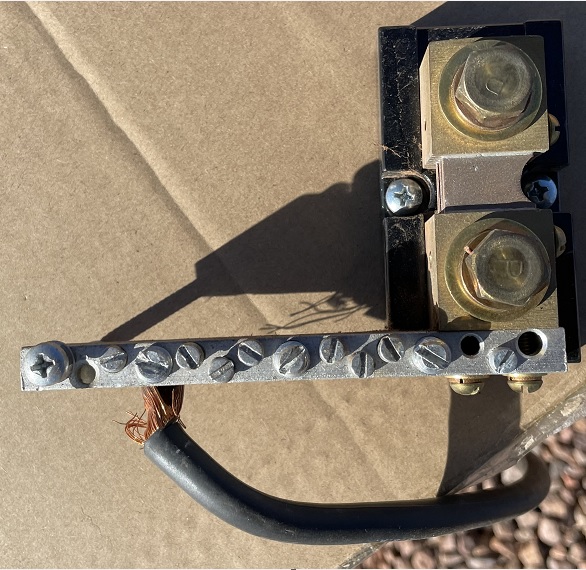
There are 6 connection points on the positive bus bar and 7 connection points on the negative busbar, one of which is a ground connection. And remember, the busbar is 1000amp, made from solid copper with plating…making it even better than copper only. You can connect batteries, loads, chargers, etc. to the busbar as needed/required.
Connection points…
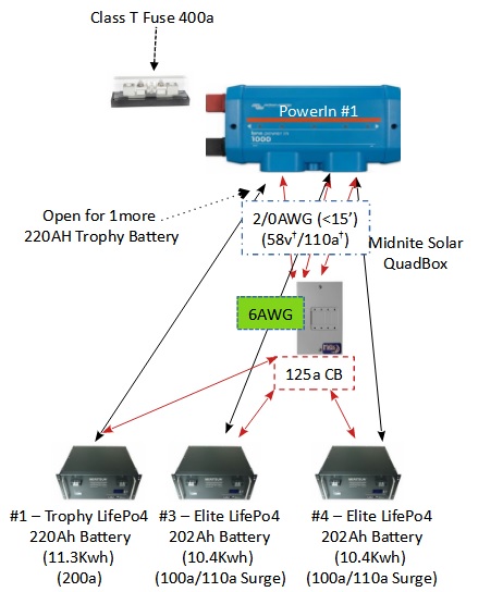
 Wiring diagram…
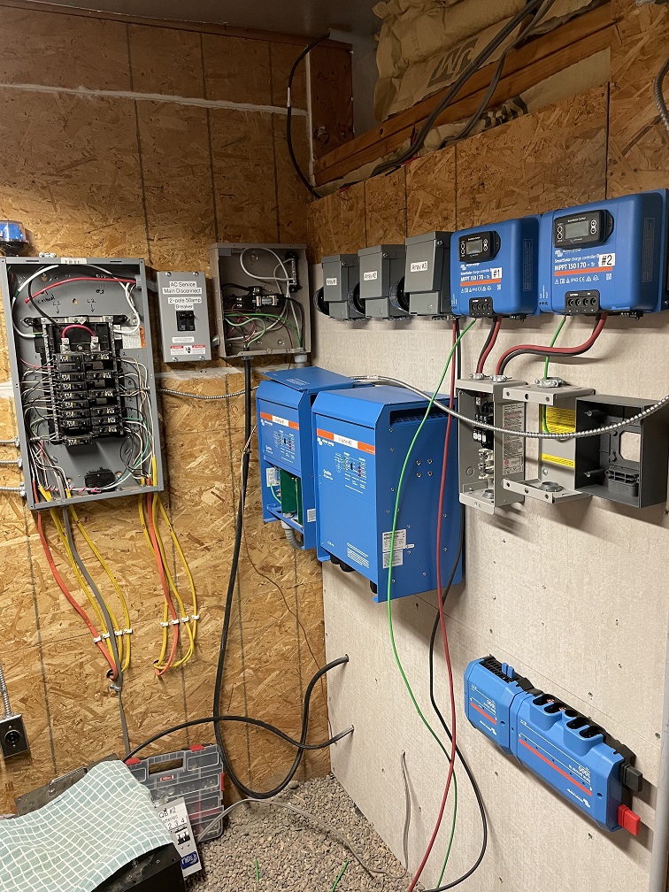
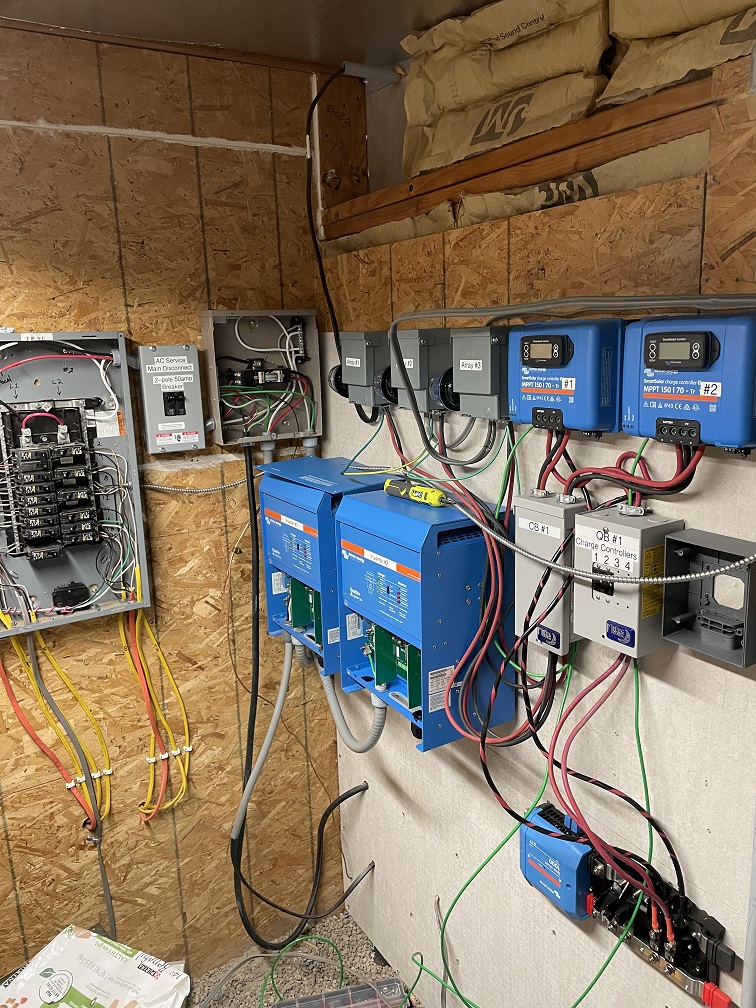
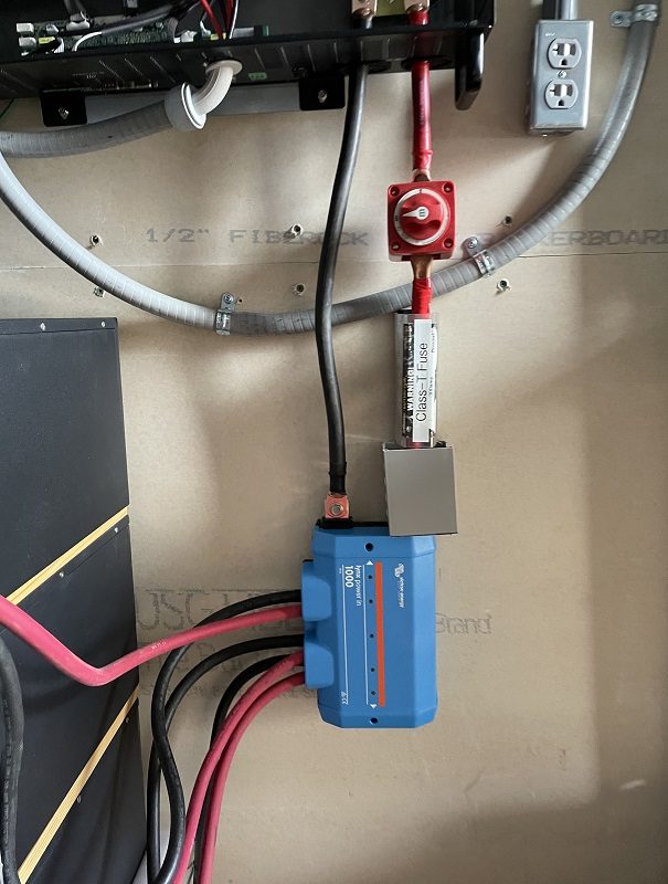
 My use of the PowerIn is two-fold; 1) using it as a busbar to connect my LifePO4 batteries in parallel, 2) using a second one as a distribution/connection point for my inverters and charge controllers. I also use a Lynx Shunt, but that is a post for another day.
Use #1 – Battery busbar system:
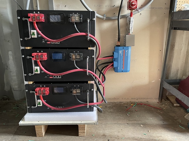
 My batteries are “rack mount” batteries, but I do not have room for a racking system. So I am placing the batteries on a very low 3″ floor stand; batteries will be 2-high, 2-wide (when completed). If I had a rack system then I would not use a PowerIn, I would use a busbar built into a rack system mounted vertically.
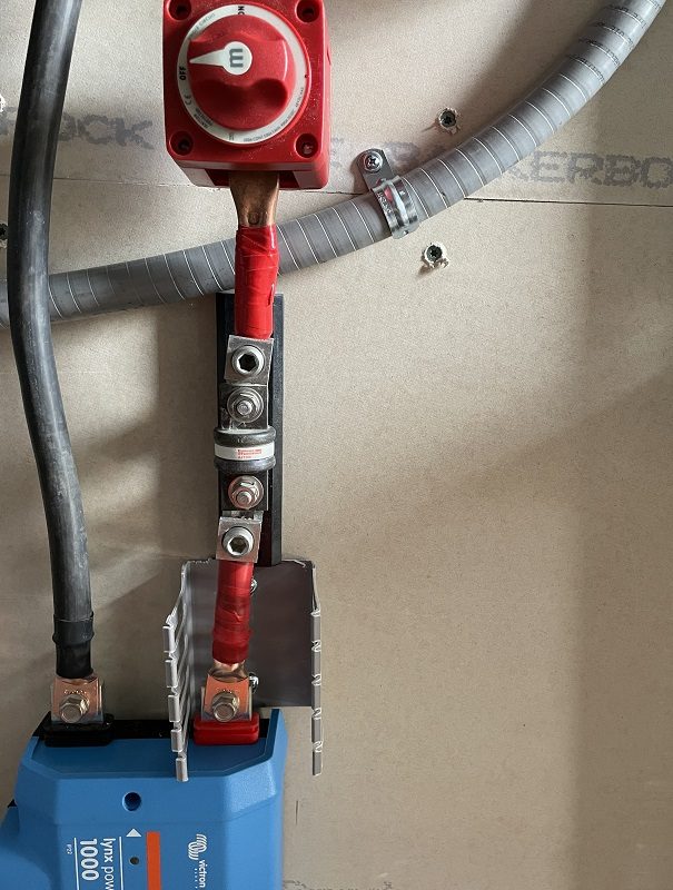
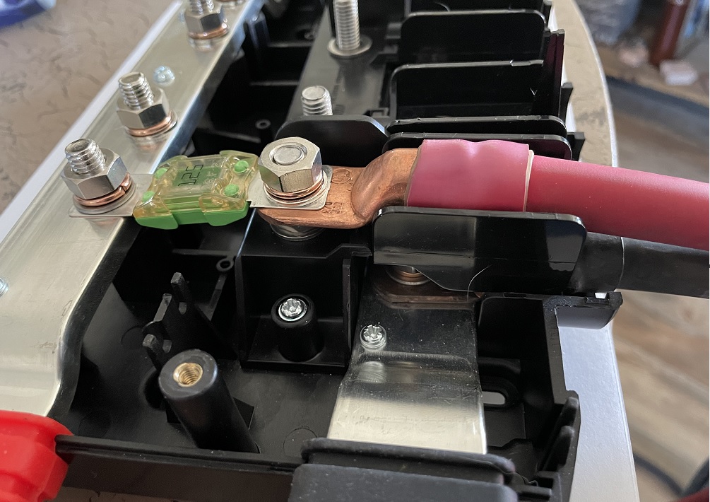
With the PowerIn each battery will have equal length 2/0 cables capable of carrying at least 200amps. When complete, each battery will also have a Bluesea 175a high current MRBF Terminal Fuse mounted on the positive terminal to each battery. The MRBF fuse will isolate/protect each battery in the case of a high-current dead short. Yes, I know I am over-engineering the system. But, I am trying to give it as much redundant protection as I realistically can.
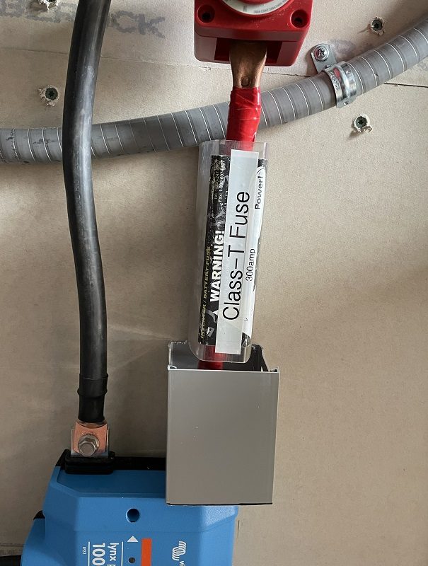
Also, connected to the external positive busbar “prong” (for lack of better description) I will attached a 400amp Class T fuse to protect the battery bank from an external high-current dead short, or, protect the system from a high-current dead short in the battery bank. Yes, I know…that means I am over-engineering again with a battery bank fuse protection and each battery fuse protected as well. But if you have ever seen a high-current dead short…well, you would want a lot of protection…a lot.
It at some point in time it might be desirable to add additional batteries to the battery bank (more than 4). If so, I will simply add another PowerIn by connecting it to the existing PowerIn and thus extending the busbar connection system. That is one of the true beauties of the Victron Lynx system…it is scalable and expandable.
The economics of a PowerIn –
First off, a PowerIn can be found on Amazon for $156.00…seems a little expensive to you? Well, let’s look at it in real terms compared to just a simple plain busbar set-up.
- Good quality busbar with cover $110.58 (this is a 600amp vs Victron 1000amp) with only 4 connections vs Victron’s 6.
- And you will need two of these, 1 for negative connections, 1 for positive connections = $221.16. And it isn’t modular.
The Victron PowerIn is $65 less expensive, more connections, more features and a very cool pretty blue cover.
But you say…I can buy two 250amp busbars for $37.99 on Amazon! Yup, you can…but look at the details…it is 250amps at 12v not the 58.4v that the solar batteries can operate at. (Oh, and other busbars are only rated at 48v maximum NOT 58.4v that the batteries can operate at.) Oh, and the busbar is plated brass NOT plated copper!
So go ahead and buy the cheap low-priced busbars and see how that works for you! If you choose this route…have plenty of fire extinguishers on hand and really good home owner’s insurance.
For those of you that want to see more of what you can do with the PowerIn…Part #2 will give details on attaching a Class T fuse to a PowerIn and how to turn the PowerIn into a fused distributor. And that info comes tomorrow!!
Let me know if you have any questions!
< click here to read Part #2 of the Victron Energy PowerIn >
Send me your thoughts, ideas, comments, questions, and concerns…
Related Articles –

 2009 - 2023 Copyright © AHTrimble.com ~ All rights reserved
No reproduction or other use of this content
without expressed written permission from AHTrimble.com
See Content Use Policy for more information.

 Day #3 come and gone!