Tip/Trap: Solar – LiFePO4 Batteries

I am hearing considerable feedback regarding a particular problem with LiFePOWER4 batteries. The problem seems to occur in larger parallel strings of batteries, 3 or more. If the batteries aren’t brought up to 100% State of Charge (SOC) every 1 – 2 days then the BMS’s begin to have significant problems reporting the correct SOC. They have also been known to have the BMS shut down a battery when it is actually above the low voltage disconnect, due to the BMS incorrectly reporting the SOC.

The only “fix” appears to ensure that the batteries are fully charged every day or two (at the most).

One of the problems I am seeing in systems are large battery storage capability but not enough PVs (solar panels) to adequately charge them on low sun days (i.e. cloudy or short winter days).

As an additional note, I looked at LiFePOWER4 batteries when I was assessing different batteries to explain my current storage capability. I was not impressed with the LiFePOWER4 batteries for a number of reasons, price being one of them, but mostly build quality and performance issues as well.


Related Articles –


 2009 - 2022 Copyright © AHTrimble.com ~ All rights reserved
No reproduction or other use of this content 
without expressed written permission from AHTrimble.com
See Content Use Policy for more information.


LifePO4 Battery SOC Charts

Yup, those are actual LifePO4 battery cells with a Battery Management System (BMS) attached to the side. In other words…a LifePO4 battery…without a fancy case around it.

In my early days of solar system design and building I had questions about when batteries were charged or not…and how much life they had left in them. Generally speaking, the voltage of a battery gives you an idea of the battery’s State of Charge (SOC).

The state of charge (SOC) of a battery is the relative charge that is present in a battery relative to its total capacity. Like knowing the amount of fuel in your vehicle’s fuel tank. When using a voltmeter to test voltage to assess SOC, for this measurement to be trustworthy, the battery must have been “at rest” (neither charged or discharged) withing the previous 12 hours.

The best way to accurately measure battery DOC is to continuously monitor voltage, amperage, and ampere hours remaining. This is a complex calculation of the energy available, energy consumed, and the energy returned to the battery in charging. It also adds the important element of time to the equation.

And to make things a bit more exciting…there is “charging voltage” and “resting voltage” that both can mean 100% SOC. Yeah, go figure right. Resting voltage is the more accurate reading to use to know the true condition of the battery. And resting mean…12 hours without a charge or discharge taking place. And in most solar systems that simply doesn’t happen because the system is constantly discharging (i.e. 24-hours a day) and/or charging (i.e. 6 – 18 hours per day while the sun shines).

So the most accurate way to gauge SOC is the continuously monitor method…and that takes special instruments. But, not too special, nor too complicated.

And here is another curve ball…

  • a 12v LifePO4 battery is correctly/fully charged at 13.6v and at 12v the SOC is just about 9% and the battery close to being ruined.

  • a 24v LifePO4 battery is correctly/fully charged at 27.2v and at 24v the SOC is just about 9% and the battery close to being ruined.

  • a 48v LifePO4 battery is correctly/fully charged at 54.4v and at 48v the SOC is just about 9% and the battery close to being ruined.

So why do they call them 12v, 24v, and 48v batteries when they don’t actually run at those voltages? I have no idea.

And another curve ball…there are “16-cell” 48v batteries and “15-cell” 48v batteries. The 15-cell version of the 48v battery is not real common and generally a good indicator of a battery manufacturer trying to hit a better price point by building a battery with one less cell and still calling it, misleading as it may be, a 48v battery.

If you are gauging a 15-cell battery you would deduct 3.4v from the fully charged, at rest, voltage of a 16-cell battery. And do so for each % rating of the 16-cell version.

To maintain a battery in healthy condition you don’t want to drop its SOC below 20%. Dropping the SOC below 20% damages the battery, meaning you are reducing it usable lifespan. Dropping the SOC below 14% damages the battery, meaning you are seriously damaging the battery. Good news is…if the battery has a BMS it should turn off automatically before damage is done. Bad news is…the battery BMS may not be set right to provide adequate protection. Good news…you can also protect the battery by setting the inverter to automatically shut down at a given voltage.

Also, charging a LifePO4 battery to 100% SOC doesn’t do the battery any favors. To keep a LifePO4 battery healthy and happy it is a good idea to charge to about 95% and don’t discharge below 20%.

In the following charts it shows the “voltage chart” displaying the voltage “curve”. Notice that the voltage curve will stay fairly flat between 110% SOC (resting) and 20% SOC, there is only .8v difference. And that is one of the huge advantages of LifePO4 battery…stable voltages throughout the discharge curve.

IMPORTANT NOTE: Always refer to your battery manufacturer for specific data, voltages, SOC, etc. regarding your particular battery. The information provide is only general information regarding LifePO4 batteries.

Individual Cell SOC & Voltages –
12v Battery SOC & Voltages –
24v Battery SOC & Voltages –
48v Battery (16-cell) SOC & Voltages –

note: you can download each image by right clicking on it.


Related Articles –


 2009 - 2023 Copyright © AHTrimble.com ~ All rights reserved
No reproduction or other use of this content 
without expressed written permission from AHTrimble.com
See Content Use Policy for more information.

DC Wire – Types, Size Chart, and Fusing

One of the things that can get confusing, but is extremely important, is knowing what size of wire to use when working with DC circuits. And once you get the wire size figured out…then trying to figure out what size fuse should you use.

So I’ve included a wire sizing chart at the bottom of the page for you to download. And I will provide a couple of tips as well. Finally, I will provide a link to a great little sizing and fusing calculator that I think makes everything much easier when trying to calculate all of this. But first, some good information to know…
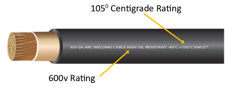
Also, it is important to note that when dealing with DC currents in solar power systems (SPS) you need a high-quality wire with a good insulation rating; 105 degrees centigrade is commonly referred to as the standard. Voltage rating should be “600V”. Also, stranded wire is best when using wire in the DC side of SPSs…the more strands the better. But, a good measure would be as follows, with each strand being 30AWG wire…

6AWG – 260 strands
4AWG – 364 strands
2AWG – 624 strands
1AWG – 767 strands
1/0 – 975 strands
2/0 – 1196 strands
3/0 – 1547 strands
4/0 – 1950 strands

Most wire wire/cable will come with rubber or rubber-based insulation. Silicone-based wire insulation is generally considered superior to rubber-based wire insulation for a number of reasons, one being a higher heat rating, up to 200 degrees centigrade. Silicone is the most fire-resistant of common insulation material, it is also highly resistant to extreme environments. Then we also see silicone as being more flexible and more compression resistant. And yes, silicone is more suitable for outdoor applications, but when running wire outdoors it’s always best placed inside a protective conduit.

Aluminum wire should not be used…period. Copper wire is the standard for DC applications due to its high electrical conductivity. However, there is even better wire than standard copper wire, tin-plated stranded copper wire. Tin-plated copper wire is noted for its longevity because of its anti-corrosion properties. And, studies show that this variety of copper wiring is able to withstand adverse weather conditions and end up lasting far longer than the standard copper wires. It’s also preferred in applications where the wire will be exposed to a high degree of humidity. And lastly, tin-plated copper wire has more electrical conductivity as compared to other varieties of copper wires. And yes, it is more expensive.

Here is a little tip for you…up-size wire recommendations one size. Yup, look up the recommended wire size…then go with one size larger. This gives you a measure of safety when deciding on your wiring. Better to have a wire/cable one size too large than one size too small. One size too small can result in more resistance and potentially melting the wire itself. And obviously, if you melt wire it is a bad thing, a very band thing…which could result in a fire.

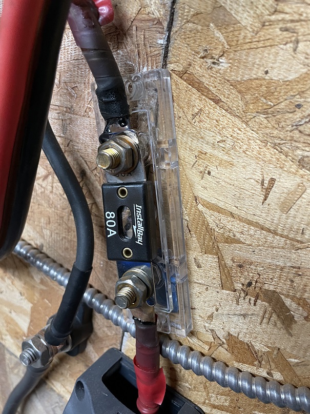
And that brings me to another tidbit of information that should be, will be, important to you…protecting your wire 
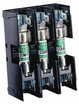
from over-current. The reason you protect your wire from over-current to prevent melting wire/cable and the possibility of fire is plain and obvious. So you put a fuse in the circuit.

Quality equipment manufacturers (Tier 1 companies) will provide fusing and/or circuit breakers internally to the equipment to protect that equipment. It is the installer’s responsibility to protect the wire connecting the equipment with fuses and/or circuit breakers.

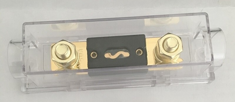
Looking at a fuse and its job is pretty simple…the job of the fuse is to melt its wire or plate element at a lower current (amperage) than the wire can handle. That breaks the circuit and stops the flow of electricity. If the fuse is rated for a higher current than the wire, then the wire become the fuse by failing before the fuse blows.

Here’s an example: 1AWG wire is rated to handle 150amps at a total circuit of under 15′ (up-sized one size). Now, if you wanted to protect that wire from failure and put a 200amp fuse in the circuit…the wire would theoretically fail at 150amps before the fuse “blew” (a.k.a. opened) at 200amps.

To avoid this problem in our example you would use a fuse of slightly less that 200amps…say 125 – 150amps. That 
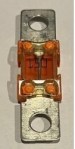
way the fuse would do its job before the wire failed and caused a potentially serious problem.

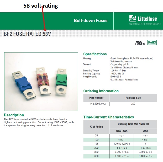
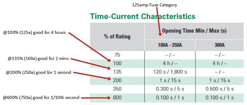
And here is another thing to consider when deciding on the correct fuse to use…its different ratings. So take a 125amp/58v BF-2 fuse from Littelfuse. It is rated at 125amps, yes? But does that mean it will blow as soon as the current hits 126amps? No. If you review the chart that accompanies the fuse you will see it will maintain integrity for different lengths of time at different currents (amps).

At 100% of rating, in this case 125amps, the fuse will maintain integrity for 4 hours. If the current rises to 135% of its rating (169amps) the fuse will still be good for approximately 2 minuets before it opens/blows. At 200% of its rating (250amps) it will open/blow at about the 1 second mark. And at 750amps it will open/blow at about 1/10th of a second. So before you decide on the right fuse looks closely at its ratings.

In our 1AWG, 200amp wire circuit at a full 200amps of current, the 125amp fuse would blow in 2 – 3 seconds

Also, notice the fuse description in the example, “125amp/58v”, that means it is rated for 125amps only up to 58volts. Meaning, if you try to employ it in a circuit above 58v it will not function correctly…as in fail.

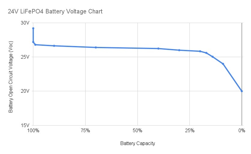
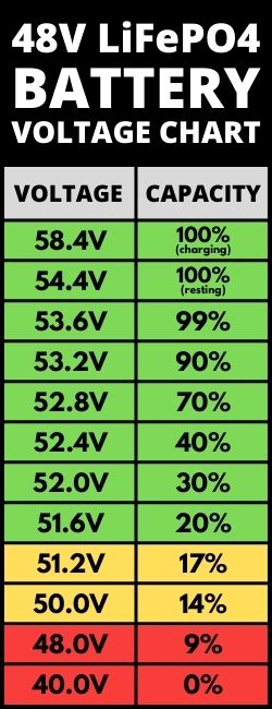
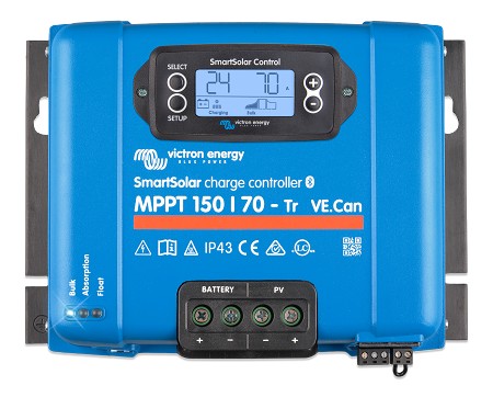
What???  And why is it rated at 58v, sounds strange, eh? That fuse is designed for 48volt solar power systems. So why the larger than 48 voltage rating? Remember that solar power system voltages can run as high as 56 – 58 volts +/- coming out of the MPPT charge controller.

Now, let’s return to the wire insulation rating. Remember I mentioned that wire should have at least a rating of 105 degrees centigrade? That means 220 degrees Fahrenheit. That is above boiling temperature of water before it fails. Silicone insulation can handle almost 400 degrees Fahrenheit before failure. So you can see one of the obvious benefits to silicone wire insulation. Now, that being said…if you are building a circuit counting on silicone’s ability to handle almost double the temps vs rubber-based insulation…you are building the circuit in dangerous country. Consider redesigning the circuit more for safety.

And there is one really misunderstood aspect of deciding on wire/cable size…the distance or length of the actual wire run. Most folks will look at the circuit and say there is 5′ between the pieces of equipment and then use that to choose the wire/cable size. WRONG!! You use the total distance of the run…round trip. The circuit is the round trip of the current. So 5′ between equipment is a 10′ distance/length.

OK, so here is the long awaited chart with one note before the displaying it…when looking at the “circuit type” use “Critical” and “3% voltage drop” and when looking at the distance, the distance is the maximum run. So when you see 15′, that means up to 15′ round trip. Notice the “round trip”…that means the wire going to AND from the two devices.

( This is a very large graphic chart. Click to enlarge or you can download it as well. )

< click here to download the DC Wire Selection Chart in PDF file format >

“Voltage drop”…don’t worry about it…just use “3%” when using the chart. But if you really want to know…voltage drop is the amount of voltage will be lost through “resistance” in the wire. Meaning the lower the quality of the wire, the more resistance, the more voltage drop, resulting in less energy being moved from one device to another. Yes, that is a bad thing, it’s a waste of energy. That is the reason to correctly size wire…to efficiently move current/power through the wire.

Now, let’s talk about the wire sizing and fusing calculator that is found on the “explorist.life” website. I like it…I like it a lot! You input the “amps”, the “voltage”, and the round trip length between the devices…then it shows you the recommended size of wire/cable to use to safely and efficiently carry that current. I like to reduce the “voltage drop” to 1.5% when using the calculator. That gives an extra margin of safety and efficiency.

There is also an option “Show Fuse Sizing Recommendations ” it gives you a great bunch of fuse information; 1)Minimum Fuse Size, 2) Recommended Fuse Size, 3) Max Wire Capacity, 4) Max Fuse Size. That is great, and critical, information to help guide you through making those design decisions. But again, I like to up-size the wire/cable one size just to be safe…and it allows for a little system expansion should the need arise.

The calculator link is https://www.explorist.life/wire-sizing-calculator/

And yes, https://www.explorist.life, run by Nate Yarbrough, has a lot of great information for you if you care to look around, including some very good videos.

TakeAways –
  • Use high quality, well insulated, stranded wire in DC circuits.
  • Up-size the wire by one size.
  • Use the right chart and/or calculator to determine the correct fuse size.
  • Ensure that the fuse rating(s) always are lower than the wire rating.
  • If you don’t understand all of this…then you shouldn’t be doing it yourself.

Related Articles –


Donation for a Battery…? WHAT ?

Yup, a couple folks asked me about the whole hidden “donation” thing. And they wanted to know more about what is was, and why I was doing it. They had found it tucked away hidden at the bottom of the Solar Home Page.

So here is the deal…my plan is to upgrade our solar power system here at the ‘glamstead’ to, as my wife puts it, upgrade our standard of living. Don’t get me wrong, we are doing just fine at this point, we just want to add more capability to power own “grid” that provides power to our place. Yes, meaning we are 100% off-grid when it comes to electricity…we produce and store own electricity via a solar power system.

So here is what the “donation” thing is all about…

Some folks have been very, very kind to me; they have understood the effort, time, and money that I have put into this website over the last 10+ years. A couple people wanted to directly help out financially with our solar system as kind of a way of showing appreciation. And, in their opinion, our fourth battery purchase seemed like the right place where they could help out.

The only major part of the solar power upgrade we have left to buy is the last (fourth) battery. The reason for the fourth battery is pretty simple; 1) we want to be able to store more power to last another day when it is cloudy outside (or during winter months) while we aren’t charging the batteries as fast as we are using the power, 2) we want to be able to run more/different appliances longer into the evening/night when the sun has gone down, 3) we also want to be able to power an RV or camper, or two, should folks show-up when times get tough.

The fourth battery will cost about $4,000 for the battery, shipping, and the wiring to hook it up. These very kind folks wanted to make a cash donation…and they suggested I do a “donation campaign” to raise the rest of the funds so we could get the battery sooner. They thought all the effort I have been putting into the website and the solar information was, could be, would be of value to folks who also appreciated what I do.

I was a little resistant at first, felt kinda like begging, but then I felt I should follow the encouragement of those folks. And it would be a huge blessing to my wife and I since we are now living on a fixed income and $4,000 is a whole lot of money to us. All things being equal, it would be sometime late next year till we had saved the funds to make that large of a purchase.

I want to thank everyone in advance for supporting the website and our efforts…regardless of whether you donate towards the battery purchase or not…thank you! You guys are the absolute best…and I am glad there are folks like you to help others.

Here is the button to do to the donation page…

Donate-3


Related Articles –


 2009 - 2022 Copyright © AHTrimble.com ~ All rights reserved
No reproduction or other use of this content 
without expressed written permission from AHTrimble.com
See Content Use Policy for more information.

Third Battery Arrived – Trophy 220E-1

note: This post should have been made 6 days after the initial post regarding the battery purchase, but it was delayed along with the first post.

Well, you know by my last post regarding my quest for a new battery was arduous but I pulled the trigger and bought a third battery for my system upgrade.

If you want to read about our solar power system upgrade you can read about here < click here >

If you want to read about evaluating and choosing the new Trophy Battery you can read about it here < click here >

If you are wondering why I didn’t buy two new batteries to round out the two I already had for a total of four batteries you can read about it at the bottom of the Solar HomePage < click here >

If you remember from the first post in this series about buying a new battery I had the batteries shipped to a friends business, his warehouse. It saved a considerable amount of money avoiding a “residential deliver” and a “tailgate lift fee”.

As soon as I got there I started popping the pallet straps, then I figured it would be good to have a video of what it looked like. Here is the video…

So the batteries (5 total – 3x110Ah, 2x220Ah) were well secured to the pallet, they shipping cases were all in great shape, no apparent damage. Trophy did a great job of designing the shipping cases. They also did a great job on shipping case placement on the pallet and strapping them down really well. And yup, FedEx handled them with care and delivered them a full day ahead of time…despite a snowstorm in the area.

I am thrilled so far…more evaluation to come!


Related Articles –


Donate-3

 2009 - 2022 Copyright © AHTrimble.com ~ All rights reserved
No reproduction or other use of this content 
without expressed written permission from AHTrimble.com
See Content Use Policy for more information.

Ordered My Third Battery !

note: this post was written on December 6th, posting was delayed for a number of reasons. As promised before, I am posting about my experience with Trophy Battery…and purchasing the third battery in a bank of 4 batteries. The fourth battery will have to wait awhile…we just don’t have the money for it just yet, the third one was expensive enough. Bummer! As I mentioned before, I researched a lot of battery options…watched numerous videos, read a ton of reviews, spoke to more than one manufacturer directly, and I even talked with a 20-year veteran of the solar business for advice. I looked at everything I could find about the different companies and their batteries. One thing was paramount…internal Battery Management System (BMS); and I wanted steel case, rack mount batteries from the very beginning. Oh, and no off-the-wall stuff like golf cart batteries. I looked into, researched, evaluated the following batteries:
  • EG4 LiFePOWER4
  • SOK
  • Jakiper
  • Ampere Time
I eliminated right away the following batteries:
  • FNS / Sacred Sun due to my prior experience with them.
  • Storz due to their high price tag.
  • Victron due to their high price tag.
Eventually I settled on Trophy Battery, the 220Ah beast to be exact. Their build was top notch, their capacity and voltages most closely matched my existing two batteries. I like the way they were designed, especially the built-in high current DC 175amp circuit breaker. I liked what I saw at every turn, more than any other battery or battery provider. Done…I would buy the Trophy Battery model 48V220C-1 48/51.2v, 220Ah. I talked with a neighbor/friend who is also a DIY solar guy to get his opinion and he thought the batteries were awesome. He wanted to order as well after we had talked for about an hour. And I am helping out a close friend and his wife who are kinda stuck in their DIY solar journey, I agreed to help them out and build their system, they needed batteries as well. Their situation wasn’t all that unusual, their system would be in an unheated Conex container. Ahhhhhhh, Trophy batteries have built-in heaters to keep them functional (i.e. charging) at below freezing temperatures. They were in as well…they wanted model 48V110C-1 48/51.2v, 110Ah…3 of them. At Trophy I spoke with Dan, the owner multiple times before placing the order. He was great and easy to work with and answered all my questions. I collected the money from the other two folks and placed the order. We did it together to save on shipping. Placing the order with Trophy was not without a minor issue. Their website locked my account and the cart would not function. Turned out to be a blessing…I placed the order directly with Dan and was pleased. The batteries shipped the next day and are due for delivery in less than a week…1 week after the order was placed. They are coming FedEx freight to a friend’s business to help save money. It saves money to have them delivered to a business vs a residence. I received multiple emails from Trophy keeping me advised of the order/shipping process. Some of the features I think are important to note:
  • 16 x EVE Power 230Ah cells
  • Heaters for charging in cold weather
  • Sophisticated programmable 200amp Battery Management System (BMS)
  • Soft start, automatic pre-charge of inverter capacitors to prevent damage
  • High current DC built-in circuit breaker
  • Front display screen for BMS
  • US based 24/7 support
  • 10-year non-prorated warranty
  • An owner’s manual…in ENGLISH!!
That is a 220Ah, 11.3watt battery for $3595.00! That comes out to 32cents per watt. Compared to many popular comparative 100Ah batteries at 34cents per watt…but the cheaper battery comes without the heaters, without the 200amp BMS,and without the internal high current DC circuit breaker! And it would take two of the 100Ah batteries and it would still fall short by 10% of the overall Ah rating…with less features. So far I am thrilled! I will keep you advised. < click here to ope a PDF file with Trophy Battery – 220E Battery Info >
Related Articles –
Donate-3
 2009 - 2023 Copyright © AHTrimble.com ~ All rights reserved
No reproduction or other use of this content 
without expressed written permission from AHTrimble.com
See Content Use Policy for more information.

Our Solar System Upgrade

There seemed to be a bunch of interest in the solar stuff I have been posting. And, I decided a couple months ago to upgrade our system. Seems like a perfect time to share more solar info, add to the solar book I am writing, and use it to double check what I am doing. I hope you get something out of it. And as always…ask questions, make comments, add suggestions, and do helpful critiques as you wish 🙂

Existing System –
  • 3.8Kw of solar panels (2 arrays of 1.5Kw, 1 array of 800w)
  • 1 x Victron Smart Solar MPPT 150/70 charge controller
  • 1 x Victron Quattro 48vDC/5000w/120vAC/70a inverter/charger
  • 1 x Victron Smart Shunt with BMV-712 Smart connected to a Victron Color Control GX
  • 2 x 202Ah LifePo4 batteries in parallel
  • On the usable house AC side we get 120vAC at approximately 41a
  • Our average power usage per day is 11.3kWh (last 12 months of history)
  • < click here to open the PDF file showing our current solar system >
Drawbacks to the Existing System –
  • We used our generator 3 days out of the last year due to low battery, approximately 40kWh.
  • We had the inverter cut out due to over discharge (drawing too much power) twice, once in June, once in July. Yup, we were using the AC’s at the time.
  • We have used two inverter style air conditioners for two summers and love them. But, we can’t run them past 10pm without risk of running the batteries too low. Fortunately, there aren’t too many nights that much AC is needed.
  • On cloudy days, or when the batteries start the day low, it is difficult to charge the batteries 100%.
  • This past year we experimented with using electric baseboard heaters during mildly cold days and evenings. They work fine, really nice. But, we can’t run more than 3 on at low settings, or two on high setting, without risking shutting down the inverter due to over discharge (drawing too much power) if/when we turn on something like the air fryer.
Proposed Upgrade to System –
  • Increase to 5.9Kw of solar panels (2 arrays of 2.235Kw, 1 array of 1.47Kw), 58% increase in power generation.
  • Add a second Victron Smart Solar MPPT 150/70 charge controller, 100% increase in potential PV to battery power generation. It will also balance the charging of the incoming solar panel power avoiding overloading a single MPPT system.
  • Add a second Victron Quattro 48vDC/5000w/120vAC/70a inverter/charger resulting in a doubling of available AC power, 100% increase. Giving us 10Kw/240vAC @ 82amps.
  • Add 2 x 220Ah LifePo4 batteries into existing battery bank, increasing our energy storage by 107%.

As a side-effect to the upgrade I will be “cleaning up” the wire layout, increasing the size of wire at strategic wiring points, improving the fusing and circuit breaker systems, and replacing important Tier 2 equipment with Tier 1 equipment. And for a major safety upgrade I will be putting up cement board (fire resistant) behind all the equipment vs the particle board I have now.

I will be posting as I go to show the “before”, what is planed for the “after”…and then what actually gets installed. Of course I will be glad to respond to any input or questions along the way.


Related Pages & Articles –


 2009 - 2023 Copyright © AHTrimble.com ~ All rights reserved
No reproduction or other use of this content 
without expressed written permission from AHTrimble.com
See Content Use Policy for more information.

TIP : Solar – Check/Tighten All Connections…regularly

A dangerous, potentially catastrophic, situation developed with my solar system and I was almost unaware of it. Thankfully I caught it in time and learned a couple lessons along the way. And that is what I will share with you today.

I run a 150/70 Victron MPPT SmartCharger…a charge controller that converts the solar panel power into usable power that charges my batteries and provides power to the inverter during daylight hours. The 150 represents the incoming voltage from the solar panels, the 70 represents the amperage (current) going into the inverter and batteries.

Normally we push about 82vDC from the panels into the charge controller. And the charge controller runs about 45 – 50amps into the batteries/inverter under normal conditions. It can run a high as 70amps in early fall or on some summer days. In the winter it can go as low as 35 – 40amps due to the solar elevation. Obviously it can go down noticeably as cloud cover increases.

When I installed the charge controller I used a standard wire size calculator for 70a, less than 10’ (round trip) circuit. That showed that 6AWG wire was plenty good enough, well within the requirements. And I wanted the circuit fused to protect the charge controller and the rest of the system, so I went with an 80a ANL fuse. And since I didn’t want the wire to act as a fuse I upgraded the wire to 4AWG, which is capable of 80a when used in a less than 15’ (round trip) circuit. Yup, all set!

About 2 months ago I was looking over the system on a particularly sunny early fall afternoon with the sun at the perfect solar elevation for my panels. I was hitting the 70a max for the charge controller. But not to worry, the charge controller will throttle the output amperage at 70a and not let it go above that limit. It does that by limiting the input power from the panels. Well, something prompted me to touch the 4AWG wire between the charge controller and the ANL fuse. Ah…hot!

For some reason, and I mean unknown, I had used 2AWG between the main busbar and the ANL fuse, but used 4AWG between the fuse and the charge controller. Please don’t ask me why, I don’t remember. I probably ran out of 2AWG and didn’t want to go buy a 1’ piece of 2AWG…but I wasn’t worried about it because 4AWG was a full size above what was required anyways.

But the 2AWG wire on the battery side of the fuse was not hot at all. Hummm….. I wrote it off as being the peak 70a current due to the sun intensity, panel angle, and solar elevation. A month later I was looking over the system again and noticed a slight discoloration to the 4AWG wire, I touched it, it was real warm, not hot, but real warm. The 2AWG below the fuse was room temperature. Problem! But I couldn’t figure it out, not to worry, the fuse would protect the system no matter what…and it was high quality 105c degree rated insulation on the wire so I wasn’t particularly.

A couple of weeks later I was once again looking over the system and noticed my red electrical tape on the aforementioned 4AWG wire, used as makeshift heat shrink, had flagged on me and an end was sticking out. 40A current showing on the charge controller and the wire was real warm. OK, I am not the brightest bulb on the tree but I realized I had to cure this problem. I wasn’t sure what the problem was…but it had to be fixed whatever it was. And since I didn’t know for sure what the problem actually was, it was my intention to replace the 4AWG wire with 2AWG, new terminal lug, proper heat shrink, and replace the 80a ANL fuse, maybe even the fuse holder if needed.

Now…left turn for a minute. While researching my upcoming system upgrade I learned that using wire ferrules on the battery wire going into the charge controller is considered “best practice” for a number of reasons, all of which made perfect sense. So I was sure that my wire overheating came from that lack of wire ferrule when I first put the system together 2.5 years ago. I now have the tool and wire ferrules…this “fix” would be a great trial run for me.

Well, the day came for the “great fix”…full batteries, informed the wife of the need for low power consumption, and gathered all of my tools and parts. Shut down the panel power input, disconnected the batteries from the charge controller, tested all the wires to make sure the charge controller was isolated, and double checked everything once again.

I went to disconnect the charge controller to battery ring terminal from the fuse and immediately knew what the problem was.

About a year ago I was reading on how to maintain a solar system and one of the points made was to check all electrical connections, then tighten or replace as needed. Ah, well, the nut holding down the ring terminal on the charge controller side of the fuse was actually loose. Yup, loose…and that was the problem.

You see if a terminal connection is loose it becomes a high resistance connection and that generates heat. The hotter the terminal gets, the weaker it becomes, and this continues until it shows up as a critical failure. But the question remains…why did it become loose? I know for a fact that when I did the initial install I tightened it correctly…period. But, as I thought about it…all the times the ring terminal connection heated up, then cooled down, then heated up, then cooled down…over and over again nearly 2,600 times. The nut simply loosened itself due to the continuous heating and cooling. And I never once checked my connections to see if everything was still tight.

Well, I replaced everything as needed, making sure everything was properly tightened. Everything is fine now, the system is running as designed, wire is room temperature, and I am sleeping a little better. Then I took the old fuse apart this morning. Oooooppppppsssssss…

See the picture for more information, but, the fuse was burnt as it should be but not 100% separated at the element. Thus, current/power was still flowing to the batteries/inverter but was several impeded.

Needless to say…I will be setting up a schedule to perform maintenance just as advised.


 2009 - 2022 Copyright © AHTrimble.com ~ All rights reserved
No reproduction or other use of this content 
without expressed written permission from AHTrimble.com
See Content Use Policy for more information.

TRAP: Solar Information Sources

So I have been doing extensive research on off-grid solar systems because I will be upgrading our system after Thanksgiving. I am adding more solar panels, a 2nd charge controller, and a 2nd inverter. Along with that a general upgrade replacing some fuses and switches with circuit breakers, plus up-sizing some wiring. And to make sure I was/am on track I am seeking out information from reliable, expert, professional sources such as the manufacturers themselves, installation engineers, etc. Oh boy, I was  surprised, disappointed, and a bit disgusted in what else I found.

Along the way I came across a whole bunch of folks, most of whom have YouTube channels, that are putting out some horrible, terrible, and potentially dangerous information. I mean some really, really bad content that on the surface sounds fine, but when compared to factual technical information is…well, pure junk. One of the problems I saw was mis/dis information about manufactures.

Let me start off by saying this…I’ve been building solar projects for over 10 years now. And, after my initial 24volt residential off-grid build here at the glamstead I realized I was working with 10-year old technology centered around lead-acid batteries. Seeing the problem rather quickly I started the first up-grade to 48v LifePo4 batteries, new inverter, etc. As I was doing the upgrade I asked the local solar dealer to ensure I had top-quality, Tier 1 equipment that I wouldn’t have to worry about. He provided Victron Energy equipment. I am so glad he did. But, back to the problem of mis/dis information about manufactures.

Part of my overall research was ensuring that Victron equipment was top-of-the-line stuff. During the research I found the real problems were far and few between. The performance problems came from under-powering the equipment itself…too small of a battery bank, too small of an inverter, too few solar panels, etc. So it was more of a system design problem than an equipment quality problem. There were two problems I found on the Internet that were serious…one inverter catching fire and one MPPT charge controller burning out. In both cases it was a wiring issue. The MPPT had a bad wire connection in the battery + wire connection inside the MPPT…installer fault. The inverter fire came from another bad wire connection inside the inverter with the battery + wire. Both times the wire wasn’t properly prepared or correctly connected to the equipment. Interesting to note…Victron did a warranty replacement on both. So the equipment was fine, the installers messed up.

Well, let’s wrap this up…a lot, most, much, of the solar information on the Internet, especially YouTube, is pure crap. It is misleading, poorly written, poorly produced, mostly DIYs, and overall just bad info. There are lots of sources out there with great information…but it can be had to sort that info from the junk info.

So Beware!

I am really concerned for folks who are doing a residential solar DIY project. This is especially true when someone is attempting a whole house, grid-tied, any system that is 48v, or any system with lithium batteries.

Why?

I don’t want to see anyone burn down their house, run afoul of their local utility company, get electrocuted with high-voltage / high-ampere system, or blow up or start a fire with a lithium battery.

So please go with only the best quality information sources, stay away from “garage experts”, and verify all information with manufactures before implementation. That is especially true with “hacks”, “shortcuts”, or “huge savings” promoting information….as well as any equipment engineered in China.


Related Articles –


 2009 - 2022 Copyright © AHTrimble.com ~ All rights reserved
No reproduction or other use of this content 
without expressed written permission from AHTrimble.com
See Content Use Policy for more information.

Our Glamstead Solar System

Here we go…I was asked to supply the info and diagram of our solar system. I hope this can be of use to folks who are thinking about going off-grid or grid-tied.

After working through the numbers I felt a 4kw – 5kw inverter would handle our needs. Yeah, I maybe didn’t get it right…thought it would meet our needs.

Later I thought about adding electric baseboard heaters…right after I figured out we needed air conditioning. So be careful on how you calculate your electric needs…then add 40 – 50%.

So here are “jpgs” for each part…

Here is the link for a PDF file of the whole thing…

< click here for Glamstead Solar Sytem PDF file >


2009 - 2022 Copyright © AHTrimble.com ~ All rights reserved
No reproduction or other use of this content
without expressed written permission from AHTrimble.com
See Content Use Policy