
 Day #9 come and gone!
Oh Boy! What a day #9 was…bitter/sweet.
I started in Saturday morning wanting to jump on first the circuit breaker upgrade that I talked about in my Day #8 post. I am using a 2-pole 50amp breaker for the inverter input side, and a 2-pole 35amp breaker for the generator (genset) input side. Why only 35amp for the genset?
I have a Champion 4kw/120vAC inverter generator that just is amazing! It is super dependable, relatively quiet, and fuel efficient. So that is my “go-to” alternative power source should our solar system go down. Just FYI…I’ve only had my system go down when I’ve shut it down, like the 6-days I shut it down to upgrade it. And I’ve used it twice to charge my battery bank after multiple days of clouds that prevented sufficient charging.
Now, the genset is 4kw, which is 33.3amps of 120vAC power. Generally speaking that is sufficient to run the house under normal conditions. But, that is running the genset at 100% of capacity and burning the maximum fuel. To keep the genset in the best running condition for the long-term and conserve fuel usage I have my inverter/charger set to only draw 20amps from the genset. That is 60% of its power generating capacity…keeping the wear & tear down and conserving fuel. At 60% is burns about 4 – 5 gals of fuel per day.
Back to the electrical numbers…So I am not going to draw more than 20amps…for now. But, to allow for expansion/upgrade in the genset I used 8AWG wire in the inlet that the genset plugs into that goes tot he inverter. The inverter can produce as much as 42amps, so 8AWG is plenty sufficient and I use a 50amp circuit breaker to protect the wiring. And yes, the 8AWG can handle 50 – 55amps of current.
The genset as I explained can produce as much as 33amps but I have it limited to 20amps. I wired the inlet for the genset with 10AWG which can handle 35 – 40amps. But, I wired the genset inlet for 240vAC input. So when the day comes when I can buy a 240v generator the inlet will be ready to convert. Yeah, that means it has a 120v inlet right now, but the L2 wire is sitting there waiting to be hooked up.
Why is all of that important? 10AWG wire can handle 35 – 40amps, but let’s be clear…I would only run 30amps maximum through 10AWG wire. But, at 240vAC that is 30amps on both L1 & L2 for a total of 60amps! Meaning I could use a 7200watt 240vAC genset…but that would be at 100%. In reality, I would probably buy a 12kW 240vAC generator and stick with my 60% rule. So all of that means…the transfer switch genset input circuit breaker is a 2-pole 30amp breaker.
That closes the book on the transfer switch upgrade. Next came some AC re-wiring.
I have a 30amp 120vAC outlet outside of the utility room where all of this solar gear is installed. I use if for heavy load needs around the outside of the house or charging my tractor battery if/when it dies. I re-ran the wire for it and got it back into the main breaker panel. Then I rerouted the power/switch/outlet for the utility room light. Good day’s work so far…then I pushed it.
I had a little more time left, not much but some, and I wanted to get more wiring in the wire ducts. About 20 minutes into that I accidentally bumped into a circuit breaker…and it flipped off. Oh boy! The alarms started going off.
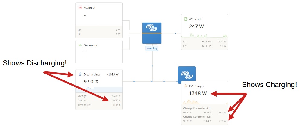
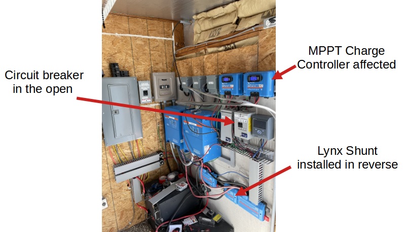
See the problem is..it was the circuit breaker that is between the power busbar and one of the MPPT charge controllers. And the problem with that…YOU DON’T EVER TURN OFF THE BATTERY POWER TO AN MPPT UNTIL YOU TURN OFF THE ARRAY POWER FIRST!
Why? Because you can ruin the charge controller and burn it out or over charge the batteries and burn them out. Thankfully I am using Victron equipment and they have a built in preventative relay that shuts down the MPPT quickly to prevent damage to either…usually.
I will shorten this down…2 hours of intense troubleshooting and research later my MPPT charge controller was back up and running…luckily. And I mean that…luck and great quality Victron equipment kept me from having a $500+ mistake/accident on my hands.
Being the risk mitigation guy that I am I was determined to prevent that from happening again. PROBLEM!
I knew I needed to cover the circuit breakers to prevent accidental bumps that would trip the breakers. But, there were no reasonably priced panels for the panel-mount breakers that I am using for that operation. After about 1.5 hours of research I found a solution that will work…a pair of paralleled 40amp 150vDC DIN mount breakers that I will mount in my Midnite Solar combiner box that I had pulled out of the upgrade design at the last minute. Those breakers will be in later this week…and get installed ASAP into the new box that will cover them and hopefully help prevent accidents/mistakes in the future.
So, if you have been following these system upgrade posts…this is the 2nd revision to the upgrade…in 2 weeks since I started.
Oh wait…I also noticed that I installed the Victron Lynx Shunt in reverse. And that explained why I was showing my batteries discharging when I was generating plenty of PV power. So now…I will have to figure out the right way to handle that.
 So what the heck is my bottom line…when you go off-grid solar you are your own power company and you better have some skills…or you will have problems.
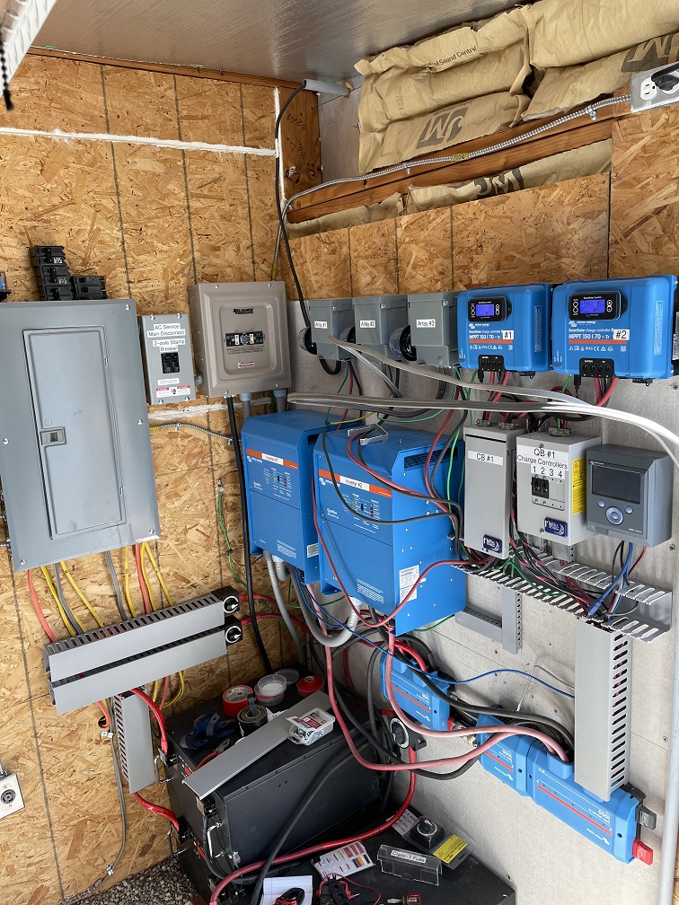
At the start of Day #9 –
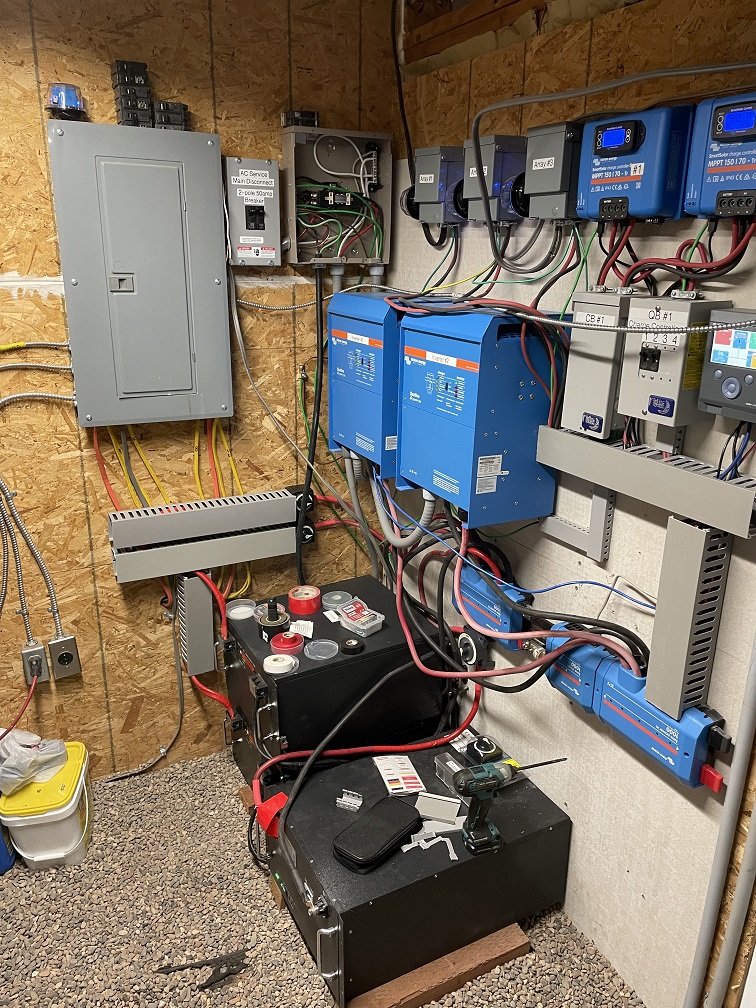
At the end of Day #9 –
 Here is the problem with the circuit breaker and MPPT charge controller…
Related Articles –
- Great Solar Upgrade – Day #1
- Great Solar Upgrade – Day #2
- Great Solar Upgrade – Day #3
- Great Solar Upgrade – Day #4
- Great Solar Upgrade – Day #5
- Great Solar Upgrade – Day #6
 2009 - 2023 Copyright © AHTrimble.com ~ All rights reserved
No reproduction or other use of this content
without expressed written permission from AHTrimble.com
See Content Use Policy for more information.
