Immediate Action Warning! (5/1/2020 – Money)

5/1/2020 – 1300

Money

With the potential extreme problems with the economy, stock market, and value of the dollar I am issuing an Immediate Action Warning – Money.

There are significant indicators that show we could see a rapid decline in stock market indicators and/or value of the dollar. Significant to the point that the dollar could collapse, and do so rapidly. There is also an increasing potential for a “bank holiday” to occur and a reset of the economy, banking system, credit markets, etc.

Possible steps to take:

  • Have cash on hand stored safely and securely.
  • If you don’t have any precious metals consider acquiring some. Silver would be my first choice, junk silver at that. There is plenty of it on eBay, or you can check with a local or online dealer. Get it in your possession as soon as possible. Do not let anyone know you are buying it.
  • If you already own precious metals and it is stored off-site, get it in your physical possession as soon as practical. Store it safely and securely. Do not let anyone know you have any or have purchased it.
  • Do not panic and dump stocks or mutual funds out of your IRA or 401k. I will stay invested in the markets through my IRA mutual funds. But not more than 33  – 50% of my total invested funds. The rest will stay in a money market fund.
  • If you are considering buying something of tangible value such as a tractor or generator, etc. do so as soon as you can responsibly do so.

Do not delay in implementing those things you know need to be done.


2009 - 2020 Copyright © AHTrimble.com ~ All rights reserved
No reproduction or other use of this content 
without expressed written permission from AHTrimble.com
See Content Use Policy for more information.

Immediate Action Warning! (5/1/2020 – Food)

5/1/2020 – 1100

Food

With the recent alarming developments in the current and potential food distribution chain I am issuing an Immediate Action Warning – Food.

I am warning against the increasing scarcity of some foods in the US. Of current specific concern is meat (i.e. pork and poultry). I have personally confirmed that there are significant problem with major food producers getting meat to the retail markets.

As US fruit and vegetable crops become available for harvesting there could also develop a shortage of farm personnel to harvest those crops. And there is also a similar potential issue getting those crops into the food distribution chain as well.

Possible steps to take:

  • Plant a garden with heirloom seeds. It doesn’t matter how large a garden, just get something planted. Prepare to harvest the seeds from your garden. The seeds may be the most valuable part of this year’s crop.
  • Begin to acquire additional meat as you would pantry items. Don’t go crazy and spend 100’s or 1000’s of dollars buying meat. But, buy an additional couple of pounds of beef, pork, chicken, or bacon. Freeze it, can it, jerk it, dehydrate it, etc. Any way you wish to preserve it is OK with me. Just get moving on it!
  • Acquire additional pantry items. I recommend a minimum of 90 days supply of normal every-day use pantry food.
  • Be creative in acquiring your food. Join a co-op, use the LDS church distribution center, go through someone you know who owns a restaurant and buys through a wholesale supplier, go direct to a meat producer and buy 1/2 a pig or beef through them.
  • Make sure your food pantry is full.

Do not delay in implementing those things you know need to be done.


2009 - 2020 Copyright © AHTrimble.com ~ All rights reserved
No reproduction or other use of this content 
without expressed written permission from AHTrimble.com
See Content Use Policy for more information.

My “Power-Box” Project – Part #2

After starting, stopping, starting again, stopping once more…then putting the project on hold it was time to get back on this project. Does that sound confusing enough?

Well, when I started building this power box project I had this grandiose idea of having all these levels of redundancy and just a heck of a sophisticated power box. Yeah, remember what the KISS principle is? Well, somewhere along the way I went brain dead.

< Read Part #1 by clicking here >

Now, in my defense, the original power box that I had built worked! It had three batteries, a PWM solar charger built in, a relay to cut-over to a second bank of batteries should the big 100Ah AGM battery drop too low. There was an auto-switch from AC to DC if the AC failed. And there was more, much more. But, when I was all done with it, it simply was way, way too much…too sophisticated.

So I sat there in my shop one evening and was looking over the power box monstrosity thinking I had developed the perfect Frankenstein Monster. But, perfect in regards to theory only. In the field it would be too heavy, too many electronic parts, too complex, and just the wrong thing for the job. So, what did I do about it? I went back to basics. I reviewed the original “mission” and then went over the “Requirements & Restrictions.” Then it became clear to me to stop trying to overkill it.

Once I made up my mind to go back to the basic use I thought I should jump on it. Yeah, life had other plans for me, I was buried in other projects and it was just too cold out in my shop so I put the whole thing on hold till it got reasonably warmer. That was last week.

Once I started back on the project it went quickly and easily. I just wanted a power box that could –

  1. Provide reliable 12vDC to any of my radios.
  2. Provide reliable 12vDC to any combination of two of my radios.
  3. Provide a reliable means to charge at least 10 handheld radios at one time.
  4. Provide 12vDC power to other electronics as necessary.

I also wanted the following capabilities –

  1. Utilize 120vAC power if it was available but making sure there was auto-switch capability to DC power if the AC power was lost.
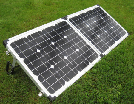
  2. Make use of a wide variety of solar charging capabilities; small 7w options all the to my dual-panel 60w solar charging system.
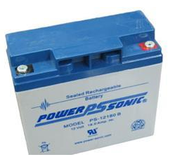
  3. Make use of a battery tender to keep the battery topped off.

Once I had that all clear in my head the “build” was pretty easy. Here is the list of components that I used –

Energizer 100Ah 12vDC AGM battery

Energizer AGM battery, Model: 31A 100 Amp Hour


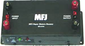
MFJ 4230MV compact 25a power supply

MFJ-4230MV COMPACT SWITCH


Super PWRgate PG40S auto-switch

Ham In The Box - Super PWRgate PG40S by West Mountain Radio


For more operational capability I added –

Powerwerx voltage meter


A cigarette power outlet

Ham In The Box - Powerwerx Panel Mount Cigarette Lighter Socket Automotive Marine Grade


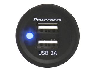
A dual 3A USB power outlet

Ham In The Box - Powerwerx Panel Mount Dual USB Socket 3 Amp Device Charger.


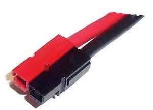
Various Anderson Powerpole chassis mounted connections


What I ended up with was exactly what I wanted. Sure, it was a little less operational time due to lower ampere hour availability, but it still met my basic mission just fine. And, it was a whole lot lighter and less complicated.

So here are the steps for the “build” –

Step #1 –

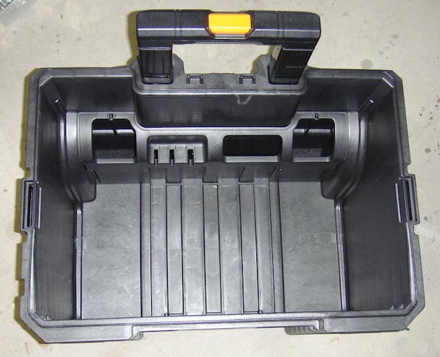
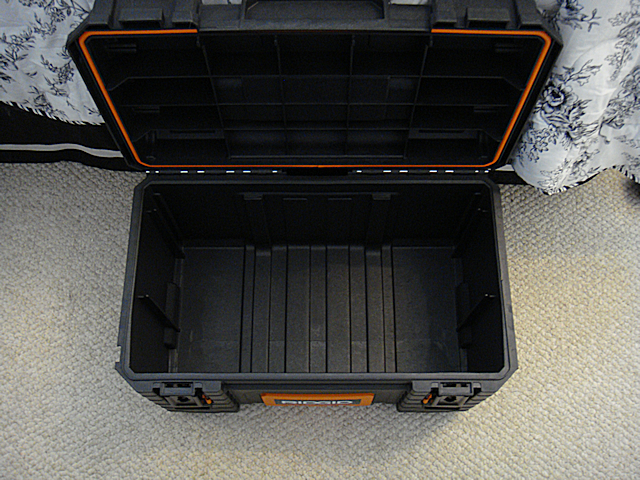
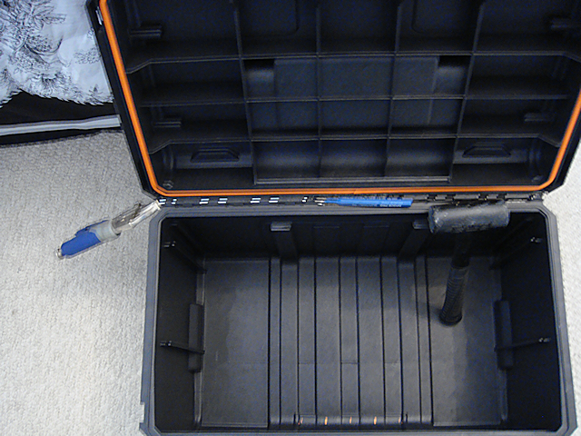
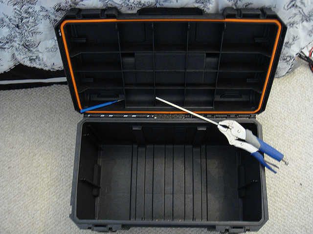
I started with an empty Rigid toolbox with wheels (model #) and added some Velcro to the bottom of the box. There is corresponding Velcro secured on the bottom of the battery. The battery weighs a whole lot! So it really isn’t going to somehow fall out of the box. The Velcro is used to keep it from moving around inside the box.

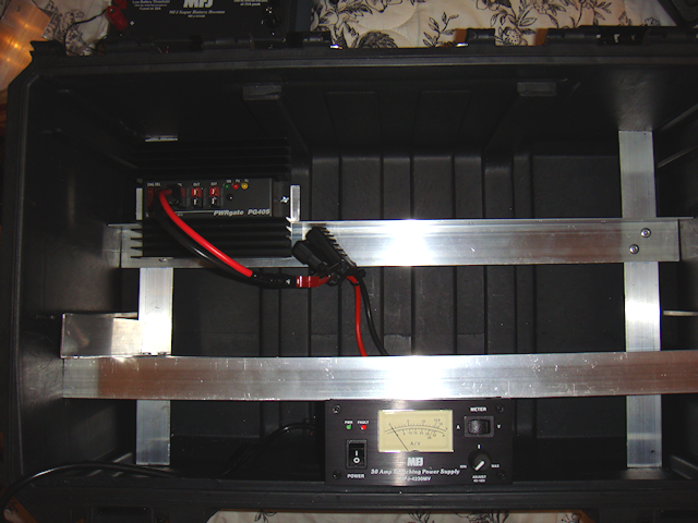
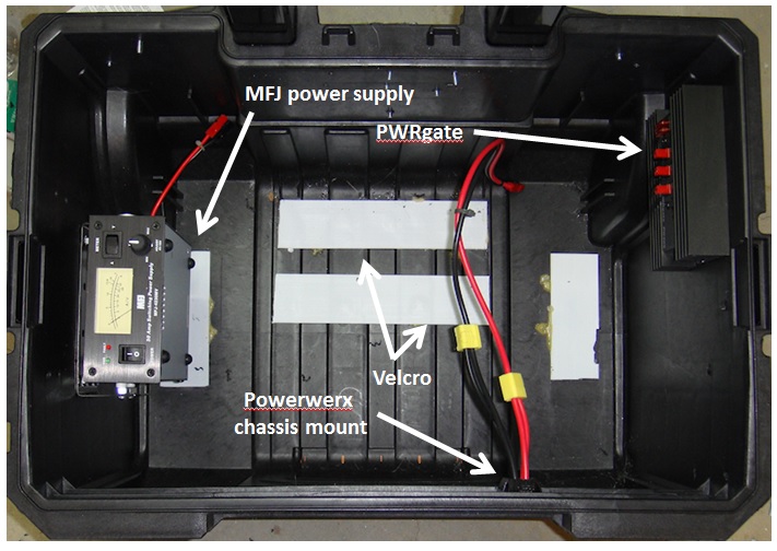
I wanted to ensure that I could get the battery in and out of the box without moving any other component and I wanted to keep the components spread out to reduce heat build-up as much as possible. It made sense to put the battery to the back of the box located as close to the wheels as possible for ease of movement. The power supply and auto-switch made the most sense to mount on opposite sides of the box.

Originally I wanted the power supply on the inside-front of the box but the mounting bracket pretty much dictated where that unit was to be mounted. With the location and positioning of each component figured out moved on to the the actual installs.

Step #2 –

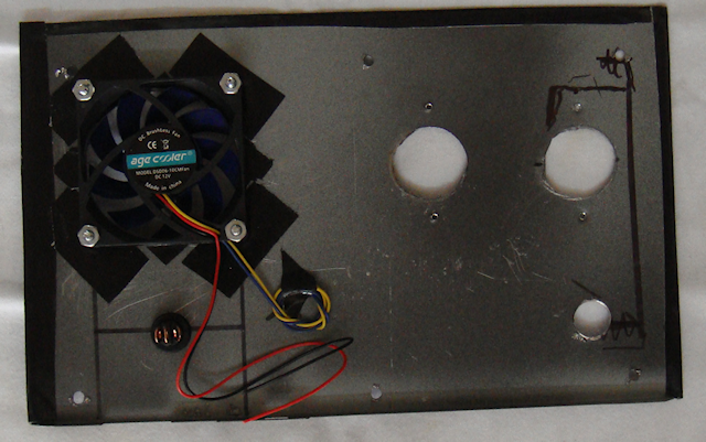
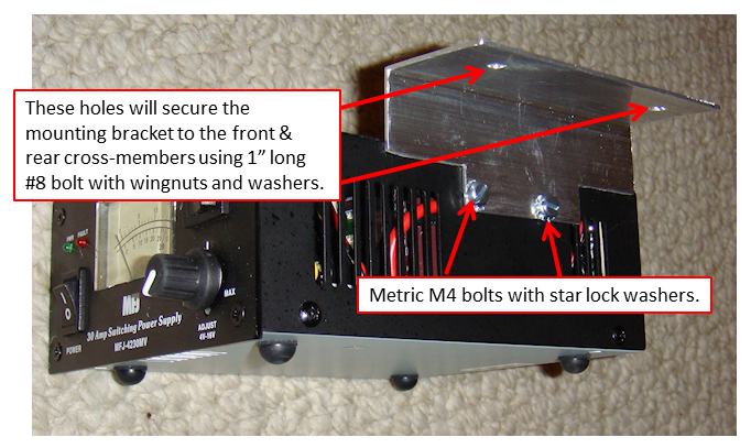
The MFJ power supply doesn’t come with a mounting bracket, and it is a little off when it comes to standard dimensions for mounting brackets. I don’t like reinventing the wheel if I don’thave to. I took one of my spare Yeasu radio mounting brackets and added spacers to make it work for the MFJ power supply. I wanted the meter to be easily read but I also wanted to maximize the airflow around and through the unit itself. Hence, mounting it on the left side of the box with the bottom facing away from the side of the box.

Step #3 –

Next came the PWRgate and its proper placement. I already had the left side used and the front of the box I had decided to use for my Powerpole connections, meter, and power supply points. By default that left the right side of the box for the PWRgate. It was simple to find a decent spot and secure it to the side of the box.

Then wired up the “power out” to the Powerwerx chassis mount.

Step #4 –

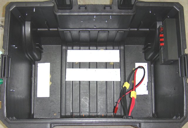
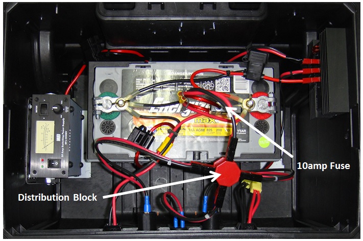
I wanted to complete one side of the power circuit so I went ahead and placed the battery in the box, wired the battery to the PWRgate, and connected the PWRgate to the Powerwerx chassis mount. All wiring is high quality 10g wire to prevent voltage/amperage loss.

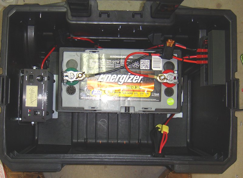
Notice that I have connected the power outlet to the PWRgate with a single 10g wire. Then off of that wire I used a connecter to splice in another 10g wire. Those are connected to the chassis connection point. Doing so gives me two sets of Anderson Powerpoles to connection equipment (i.e. radios) to. The 10g wire is more than enough to carry the carry the amperage.

Step #5 –

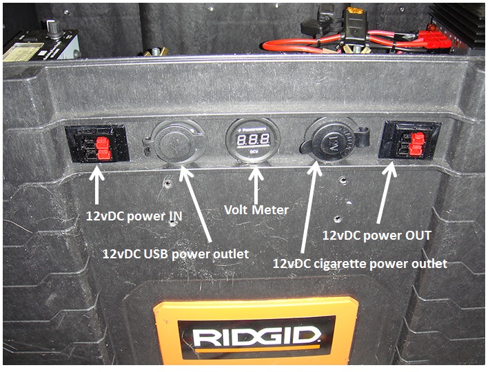
At this point I tried to implement some logic…power to the battery. So I installed another Powerpole chassis connection point on the left side of the front panel. This would be my connection to charging devices. Those devices could be solar chargers, a battery tender, or even another power box.

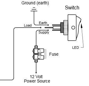
Notice that I ran the power in lines directly to the battery for the lowest amperage loss. But, I did place a fuse inline to protect the battery from any surge coming into the box.

Step #6 –

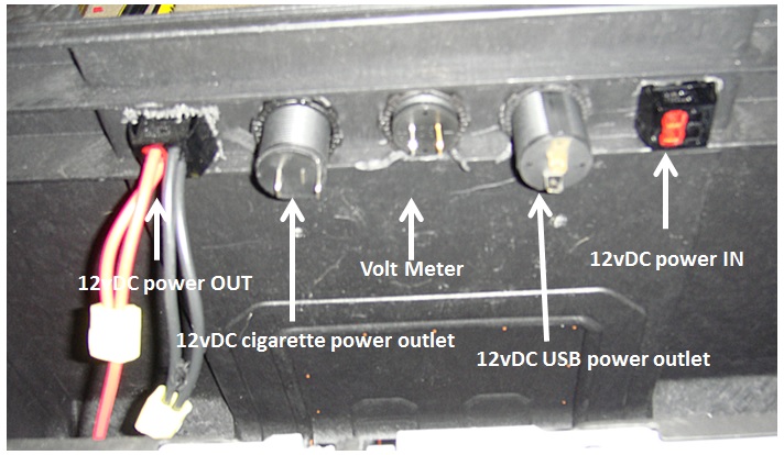
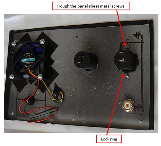
I wanted to be able to monitor the battery and get a feel for usage rate, remaining operational time, etc. So in comes the Powerwerx voltage meter. It was a simple install direct to on the front of the box. I located it in between a couple of horizontal structural pieces of the box. I used a 1-3/16” hole saw then used the standard plastic ring to secure the voltage meter to the box.

Step #7 –

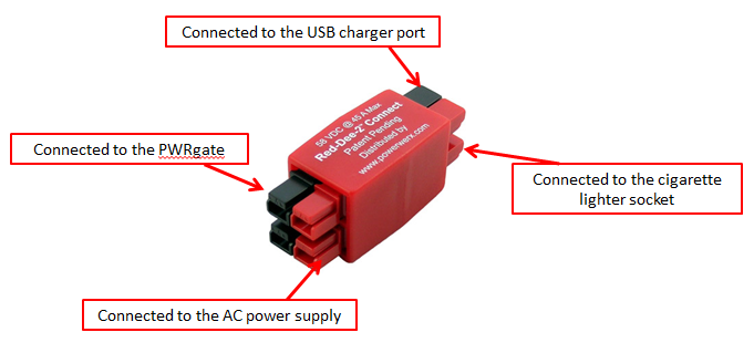
As I mentioned earlier I wanted to add both a USB power outlet and a cigarette power outlet. The later provides a connection point for a wide variety of existing power options for various electronic and electrical equipment.

I prefer Powerwerx power outlets, one reason is the same diameter as the Powerwerx voltage meter. I placed a power outlet on either side of the voltage meter simply for atheistic. What I had to do was work it so the protective caps on the power outlets would open and not interfere with or be impeded by, the lip of plastic on the box itself.

Step #8 –

I had original thought to hook each of the power points and the voltage meter directly to the battery. Then I started to figure out having to fuse each line, etc. That is when I fell back to a Powerwerx distribution unit. Fuse one line going in, attached the two power outlets and the voltage meter and I would be good to go.

Step #9 –

I put the multi-meter to everything and it all checked out fine. Checked the voltage meter against the multi-meter and it checked out fine. Now it was time to test it out.

I was working on reviewing a dedicated 12vDC battery charging cradle for Baofeng UV-5RA so I figured why not test them both…and I did. I plugged the charger into the USB power point…fine. Then I plugged it into the cigarette power point…fine. I left it in there for four hours and it charged the radio battery up with no problems…no smoke, no smell of burning wires, and didn’t even burn up the charger base. All is good!

Next test was plugging in my battery tender that I am also reviewing, and it went right to work analyzing the big 100Ah Energizer battery, then went to charging it. I let it go overnight and came back in the morning to see it had topped off the battery and the tender was doing its thing to keep the AGM fully charged and ready.

A couple days later came the solar panel testing. Once again, everything performed exactly as designed. One note to make would be that whatever solar charging system must have its own charge controller since one is not built into the power box.

Finally came the AC power test. I plugged in the MFJ power cord, turn it on, and up comes the MFJ power supply just as it is supposed to. I dialed in the right DC voltage (13.4) to the PWRgate and all was good…no blown fuses and power coming out just as designed.

Then came the “switch” test. I put a load on the power box made sure the AC was working just fine and that the battery was standing by. Then I turned off the AC power. The PWRgate auto-switched from the AC power over to the DC power from the battery without any interruption of power. I did notice the power dropped from 13.4v to 13.2v. But that is to be expected when running off of the battery.

Everything worked exactly as I had planned and hoped it would.

Next test will be draining the batteries from 10 Baofeng UV-5RA radios. Then I will use a variety of DC charge adapters hooked into the Baofeng charging bases to see how long it takes to charge up all 10 batteries and the draw-down on the 100Ah AGM battery.

Then I will draw-down the 100Ah AGM battery and hook up the AC power to see how long it takes the PWRgate to bring the AGM battery back online and back to full power. But in the meantime, I leave the MFJ power supply on and it will keep the 100Ah AGM battery fully charged and ready to go.

Stay tuned for more testing results and another idea or two!!!

2009 - 2020 Copyright © AHTrimble.com ~ All rights reserved
No reproduction or other use of this content 
without expressed written permission from AHTrimble.com
See Content Use Policy for more information.

Immediate Action Warning! (5/1/2020 – Violence)

5/1/2020 – 0900

Violence

With the recent armed citizenry presence in the Michigan capital building and the resulting confrontation and previous widespread anti-stay-at-home protests I am issuing an Immediate Action Warning – Violence.

I am warning against the increase of violence in the USA as a result of Draconian government actions to restrict rights, liberties, and freedoms of American citizens under the guise protecting the public. There is also an corresponding increase the potential of violence of protestors, specifically armed protestors, who confront law enforcement personnel.

There is also a general potential for increase in violence as food becomes more scarce, medications become more scarce, more widespread use of anti-depressant and anti-psychotic medication, self-medication, and stress from the continued COVID-19 restrictions and related issues.

Possible steps to take:

  • Review your defensive weapons and ammunition situation. Do no delay in purchasing additional ammunition supplies, weapons, magazines, and/or weapons.
  • Make sure you have a serviceable tactical vest and accessories.
  • Clean weapons, magazines, and ensure your ammunition is serviceable.
  • Have your weapons readily available but safely stored.
  • Avoid protests.
  • Avoid confronations with law enforcement personnel.
  • Support Peace Officers.
  • Create/join a Neighborhood Watch program or security group.
  • Talk with other like-minded folks about the current and potential need for security.
  • Keep your Situational Awareness high at all times.
  • Review how you could improve the security of your home. Install a basic, stand-alone security system such as SimpliSafe with cameras, external sirens, etc.

Do not delay in implementing those things you know need to be done.


2009 - 2020 Copyright © AHTrimble.com ~ All rights reserved
No reproduction or other use of this content 
without expressed written permission from AHTrimble.com
See Content Use Policy for more information.

SitRep – 05/01/20 – WARNING !

OK, gonna be down & dirty…a lot of ground to cover and Immediate Action Warnings coming out later today. To get the information out I will provide less background than normal. So either believe me or not. Do your own research or not. Prepare or not. It’s all up to you.

Coup Taking Place –

Yeah, we are back to that. Remember, I was right back in 2017 when I broke the news, named names, and laid it all out…I was 100% right then…and I am right now.

The deepstate, democrats, the FBI, and others have been unsuccessful in overthrowing President Trump, not for lack of trying. However, they have not been savvy enough, Trump has been smarter than them and used direct contact with the public to overcome his enemies. But all the evidence I am seeing now is Trump is not, and cannot, beat COVID-19. Well, more specifically…the “use” of the COVID-19 panic by his enemies.

I have written about this upcoming election in pretty plain terms…everyone loses. I believe Trump has now less that a 10% probability of winning. The latest evidence, with the numbers to prove it, show that if the US uses mail-in ballots for the election this fall Trump would have 0% chance of reelection.

Dubbed “cheat by mail”, numbers show that Virginia has 11,000 dead people ready to receive mail-in ballots, Pennsylvania has 800,000 inactive voters that would receive mail-in ballots. If I just make a conservative low-end estimate of the potential voter fraud using a real-life example of PA, that means there are approximately 13 million inactive/dead/ineligible registered voters on the books in the USA ready to receive mail-in ballots.

But, let’s say I am off by half and there is only 6.5million. And  make it even more fair…only half of them are fraudulent when election day comes…that is 3.25million mail-in ballots that are used fraudulently in the 2020 Presidential election. Remember, Trump lost the popular vote by millions in 2016. Think about this…in 2020 he loses by millions more…let’s say he loses by 4 – 5 million votes that include the fraudulent mail-in ballots. Do you think there is any chance the Electoral College saves him? Even if the Electoral College somehow did swing in his favor…would the majority population accept it? Nope!

Electronic balloting would be even worse by an order of magnitude.

The coup against Trump has changed, Trump is losing and Trump has little chance of reelection. At least at this point.

And there is serious talk now that the Republicans could lose the Senate. Well, if they do, which I believe stands at about 50/50 probability right now, then the country will end up in another revolution within 4 years…period. And in the meantime the Democrat controlled federal government would push an all-out socialist/Communist agenda.

War –

Within the last 48 hours China claimed that it “expelled” a US warship from the South China Sea. Let’s disregard the truthfulness of it for a minute and just focus on the claim…it is frightening…at least from a “war” prospective. And let’s not forget that they are promoting more and more that COVID-19 is a US bio-weapon. I am telling you…China is pushing us towards an armed engagement at best, an all-out war worst case.

And of course they are having help from the Russians…who are helping to destroy our energy industry, specifically the oil industry, by pumping oil at an historic rate vs. demand driving oil prices down…and shuttering American oil company doors in the process.

Economy/Fed –

The Federal Reserve (Fed) has admitted to creating nearly $7tillion dollars of fresh debt in the last month+. However, nowhere do you find a corresponding rise in the US national debt to match it. And the only way the Fed can raise money to pump into the economy is by creating US debt. So what has happened? It is “off-book” meaning there is no accounting of the Fed on how it raised that money and the US government is not admitting its involvement. That should shake you to your very foundation.

But it gets worse…the Fed is admitting to an increase of 40% of its assets. Yes, you read that right…it’s assets. Those assets include; T-Bills, municipal bonds, bank loans…and stocks. Yes, stocks. So part of this whole mess means that the Fed is becoming rich. And as the stock market continues to improve the Fed gets richer and richer. And who is the Fed?  A private corporation of private banks.

Remember I mentioned the largest transfer of wealth in the history of the US through the COVID-19 panic? Well, now you are seeing a small slice of it. But that is not the significant part. The Fed creates nearly $10trillion (actual number vs admitted number) to pump into the economy and where is the corresponding debt accounting for it? Nowhere to be found…but that is not worst part. The worst part is the mammoth devaluation of the dollar. The actual value of the dollar has been devalued by 30 – 40% in the last 6 weeks. How? The Fed simply created more money, $10trillion, with ZERO underlying increase in anything tangible to back-up that “funny money” creation. It was created out of thin air!

25million people have become unemployed in a little over a month. Let that sink in for a minute. How are they collecting unemployment benefits now? How long will they stay unemployed receiving those unemployment $’s? How does the US pay for the $’s? How does the US get 25million people back to work?

In the last 10 years the USA has created a little over 20 million new jobs. So I ask again…how long does it take the US to put those 25 million people back to work? And what happens to those people and the US economy while trying to get those people backs to work?

Food –

I’ve written about the food chain issues, I warned about food shortages, I’ve given you warnings this could turn into a world-wide crisis. It’s here…or at least the beginning stages of it. Want proof?  President Trump just a couple days ago invoked the Defense Production Action to keep food production going. I verified yesterday of the seriousness of the problem. Sure, we’ve heard presidents of companies, including Tyson Foods, talk about closing plants, lack of employees, huge reduction of product going into the food distribution system. Yesterday I personally confirmed it with my sources. Pork is the first hit, poultry is close behind, beef not too far off.

There will be increasing food problems…mainly food getting to the stores for retail consumption.

Summary –

Probability of violence, war, food shortages, coup, etc. have all gone up significantly!  Urgent to prepare now as much as you possibly can.

Avoid prepper fatigue, news overload, and don’t over react, panic, or scare others…just step up prepping now!

Watch for Immediate Action Warnings.


2009 - 2020 Copyright © AHTrimble.com ~ All rights reserved
No reproduction or other use of this content 
without expressed written permission from AHTrimble.com
See Content Use Policy for more information.

My “Power-Box” Project – Part #1

I built my “ham-in-the-box” radio kit that contains my Yaesu FT-8900R for use during emergencies, disasters and anytime there Ham-in-the-box mobile ham radio set-up with Yaesu FT-8900ris a “grid-down” situation. And it works like a charm, I love it. Read more about it here < click here to read more >.And as long as there was normal 110 vAC utility power then I was all set because the unit has a MFJ Enterprises Inc. MFJ-4230MV AC power supply built into it. But what about Ham In The Box - MFJ Enterprises Inc. MFJ-4230MV COMPACT SWITCHwhen the power goes off? Yeah, of course I accounted for the possibility, and this article will address the “power out” situation.

One thing that is a true “unknown” when the power goes out in emergencies and disasters is, how long will the power stay off. I tried to get a good feel for it but just couldn’t come up with a valid time estimate. That being the case I just counted on it staying off…till it came back on. Yes, I am serious. So that led me to the easy answer for alternative power, solar.

I know that for some folks in some areas of the country that solar is a limited choice. And I can appreciate that so I tried to build into the system little redundancy that might help overcome the solar-challenges that people have in some parts of the country and world. Here in the southwest it is not a problem at all so it is a perfect solution for me.

So, as always, let’s define the mission for this alternative power source. The unit must be able to:

“Provide sufficient power to allow the use of the emergency radio kit for at least 40% of any given 24-hour period. During which transmission power usage will be approximately 20% of that time period.”

Requirements & Restrictions:

  1. Had to be very reliable.
  2. Had to come from readily replaceable parts.
  3. Had to have at least levels of redundancy.
  4. Had to be usable stand-alone or in conjunction with other equipment.
  5. Should be transferable to other equipment as power source.
  6. Should be able to charge other electronic components via cigarette lighter and USB ports.

In easier to understand terms: I want my radio to be operational for 6 hours per day, of which about 70 – 80 Yaesu FT-8900r Quad-Band Ham Radiominutes will be time when I am actually transmitting. That is pretty aggressive for transmitting time. My Yaesu FT-8900R uses a maximum of 8.5A during transmission. So I figure a 60 AH (ampere hour) rated AGM battery should handle the load with a fairly decent margin of error. So I went with a 100 AH AGM deep cycle battery to allow myself plenty of wiggle room. But that isn’t all.

One of the problems are those times when usage exceeds what your expectations were. I really want to make sure that I have enough “reserve” power to handle the radio usage when the demand is at its peak, such as the early stages of a disaster or during an “incident within an incident” occurrence. I could have simply bought a higher rated AH battery. But that is putting all my eggs in one basket; if that battery takes a dump then all of my power is gone. Hence, the whole concept of redundancy, two separate battery banks; 1) the 100 AH battery, 2) the other is 36 AH of AGM battery power (two x 18 AH batteries). The two separate battery banks are not connected.

The large 100 AH battery is an Energizer AGM battery, Model: 31A 100 Amp HourMAX. And that bad boy is big and heavy. I recharge it using a portable, folding 60w solar panel set-up. The charger controller unit has a “low voltage disconnect” built in. That unit prevents the battery from becoming too discharged and thus damaging the batteries. But I use it to trigger a relay that trips when the batteries become too discharged. And when that relay trips it switches over to the other set of batteries (two 18 AH PowerSonic AGM batteries).

When that switchover is made the larger 100 AH battery can then recharge without any drain on the battery. Once it comes back up to a full charge then the relay kicks again bringing the 100 AH battery back online. That also means that the smaller battery bank goes off-line. And to keep those two 18 AH batteries charged up I have another dual 60w solar panel set-up.

But it doesn’t end there. Remember that the Ham-In-The-Box has a PWRgate built into it? Yup, that is the unit that Ham In The Box - Super PWRgate PG40S by West Mountain Radioswitches between AC power and battery back-up. That makes it nice if the regular 120 vAC utility power goes out it switches automatically over to battery back-up. Sweet, eh? But there is a bonus to the PWRgate…it is also a battery charger when on AC power. So it will maintain the 100 AH main battery anytime AC power is available.

So let’s review the power options for the Ham-In-The-Box and Power-Box combination:

Option #1 – There is normal utility company 120 vAC power available. The Ham-In-The-Box runs off that power and keeps the 100 AH primary battery fully charged. If the AC power goes off the Ham-In-The-Box automatically switches over to the Power-Box.Honda EU2000i Generator

Option #2 – I can hook up my Honda EU-2000i which then supplies AC power to the Ham-In-The-Box and keeps the 100 AH primary battery fully charged.. If the Honda shuts down the Ham-In-The-Box automatically switches over to the Power-Box.

Option #3 – The Ham-In-The-Box is running off of the primary 100 AH battery in the Power-Box. A dual panel 60w solar system is charging the 100 AH primary battery. Also, a dual panel 60w solar system is charging the two back-up 18 AH batteries. If the primary battery drops below an operational charge (goes dead for operational purposes) the system automatically switches over to the Power-Box back-up batteries.

Option #4 – The Ham-In-The-Box is running off of the Power-Box back-up batteries. A dual panel 60w solar system (or a single 30W panel) is charging those back-up batteries. Another dual panel 60w solar system is charging the 100 AH primary battery bringing it back up to full charge. Once it is up to full charge the Power-Box switches back over to using the primary 100 AH battery. And the Power-Box back-up batteries are then being charged back up to a full charge by the dual panel 60w or single 30W panel solar system.Schumacher SC-10030A battery charger to

Option #5 – I can use the Honda EU2000i with the Schumacher SC-10030A battery charger to recharge the 100 AH primary battery (approximately 2 – 3 hours) while the Power-Box back-up batteries are supplying power to the Ham-In-The-Box.

Option #6 – I can use the Honda EU2000i’s 12vDC outlet and plug a cord directly into either solar panel input port on the box and recharge the batteries directly.

I am sure there are more options that would work with this but these are the ones that make the most operational sense to me for an emergency, disaster and “grid-down” situation. But let’s now look at Power-Box and its design and components.

Let’s go over the actual box first. I chose the Rigid Professional Tool Storage System. This “system” is a group Rigid Professional Tool Storage System 22" Too Boxof very sturdy tool boxes designed to work together. The base unit is the Mobile Gear Cart. It is the box that all the other pieces ride on. It measures out at: 22” x 18” x 19”. That is plenty large enough for holding all three batteries. And as an added bonus, the storage box has wheels which are extremely important since the batteries are heavy. The storage box is also heavy plastic making it pretty much dirt and watertight.

Now that we have the actual storage box, I will list the batteries that I choose:Energizer AGM battery, Model: 31A 100 Amp Hour

  • Battery #1 – Energizer Max AGM. 100 Ampere Hour, measures 13” x 7” x 9.5” and weighs in at an impressive 60 – 65 lbs (+/-).
  • Battery #2 & #3 – Powersonic Battery TY12-18. Each battery is an 18 Ampere Hour, measures 7” x 3” x 6.75” and each weighs 13 pounds.

The combined weight of the batteries alone comes in at 85 – 90 pounds. So far the storage box can handle the weight just fine. Yeah, you are going to have to have help lifting it into the truck or SUV. That’s what friends are for 😉

For recharging the primary 100 AH battery here is the list of components:

  • Dual 30w solar panels set-up as a folding, portable kit. (Glowtech System)
  • Morningstar SL-20L-12V charge controller.

I went with a system from Discount Solar. The price was $135 and that included shipping. The portable system comes with a charge controller but not the MorningStar SL-20L-12V. The relay disconnect is integral to the system I am building so I simply by-passed the charge controller that came with the system. I did leave the charge controller on the unit for flexibility. I switched over all the internal wire connections to Anderson PowerPoles to be compatible with everything else I have. I will give detailed steps a little later, for now I am just listing the parts.

For recharging the back-up 18 AH batteries here is the list of components:

This is a straight up system purchased from GoalZero a couple of years ago. The equipment is top-notch, high-quality stuff to be sure. Unfortunately you are paying for the GoalZero name. Don’t fall for it. At the end of this series I will do a Q&A (FAQ) section and provide a tested alternative system that is a whole lot less money. But for now I am going with what I have on-hand. And I did the same thing with this GoalZero set-up and the wiring connection, I switched them all over to Anderson PowerPoles to be compatible with everything else I have. I will give detailed steps a little later, for now I am just listing the parts.


2009 - 2020 Copyright © AHTrimble.com ~ All rights reserved
No reproduction or other use of this content 
without expressed written permission from AHTrimble.com
See Content Use Policy for more information.

My “Ham-In-The-Box” Project – Yaesu FT-8900R Go-Box – Part #3

Ham in the box, ham-in-the-box, field deployable ham radio, ham radio in teh fieldnote: This article first appeared in May 2015.

In Part #1 (posted day before yesterday) of this series I covered the mission of this Ham-In-The-Box project, requirements and limitations, and the initial challenges that I faced. I also outlined each piece of equipment that would make up the final product.

In Part #2 (posted yesterday) of this series I started relating the actual step-by-step build process. I went from prepping the box itself, building the internal frame and getting all the way through installing the remote head to the radio.

In this post I will finish out the building of this project. It was a great project, took much longer than I expected, I picked up some valuable experience and knowledge, and I learned another great lesson along the way. But when it was all over, the project functioned exactly as designed!

Just a reminder of the mission of this project –

To be able to rapidly field deploy a Ham radio, for which I am licensed to use, in the event of any emergency while maintaining a secure and protective storage environment.

~ The “Build” (continued) ~

Step 9 –

This was one of the weirdest parts that I fabricated, the front panel frame. I wanted the frame sturdy, rigid but not heavy. And I couldn’t have it too large or it would get in the way of the fan and other accessories. So I went with 3/4” angle aluminum. While I was measuring the different pieces I found there was a small “notch” or pocket in toolbox’s corner that a piece of the aluminum fit into perfectly. So I took advantage of that and used it to hold the frame in-place and semi-attached to the toolbox. The side benefit was making the whole structural frame kind of like a part of the toolbox without really attaching it. So that is the reason for the one slightly longer side to the frame. If you are looking at the box with the lid opening towards you, the longer leg would go into the notch on the front left side right under the “lip” of the toolbox. I used rivets to secure the pieces.

front view of frame


Then I was working on the solution to attaching the front panel to the frame. I really wanted to be able to remove the front panel to access the components underneath. But exactly how to do that securely while maintaining convenience was a bit difficult to figure out. Then it dawned on me to use JB Weld to bond the bolt heads to the frame. Then it was a matter of drilling out the holes in the front panel to match the bolts.

rear view of frame


Note: The 2″ notch in the front panel frame was not intentional. When I was laying out the frame and the front panel I forgot the “offset” from the left side of the box and didn’t line-up the fan to the frame correctly. I had to cut the notch so the fan wouldn’t interfere with the frame, or visa-versa.

Step 10 –

I really wanted the front panel to look sharp as well as be functional and lightweight. I went shopping for possible materials and found everything expensive. Then a moment of inspiration! I headed off to the local Goodwill and purchased a used VCR with a metal case. The metal that the case was made of was sturdy steel, thin, and a nicely painted black with a bit of texture to it. Perfect!

front


rear


Note: I used masking tape place over the metal to help prevent damage while drilling the hole. I also used a good hole-punch and gave it a sharp whack with a hammer to make a serious starter hole so the drill wouldn’t “wander” when I was starting the hole.

I used Gorilla Tape to finish off the edges and give it a slightly cleaner look than rough-cut exposed edges. Yes, I like Gorilla Tape better than Duct Tape.

The fan had to be positioned directly over the PWRgate to blow air directly at its heat sink, so I had little choice to its location on the front panel. Then I mounted a switch next to it. I figured there would be times when the air movement might not be required so why not have the capability to turn the fan off. When I attached the fan to the back of the panel I used Gorilla Tape around the hole to create a bit of a “stand-off” from the metal panel to make sure the fan blades didn’t come into contact with the metal. The tape also works a little like a rubber washer absorbing vibration from the fan. To cut the hole for the fan I used a hole saw with the correct diameter cutter. Using a hole saw made a much cleaner hole than other methods. The switch hole was drilled out with a regular drill bit as per the instructions that came with the switch.

The next requirement was the “through the case” antenna lead connector. I thought at first about just having it loose and connect it. But then I thought I wanted the box to look as professional as possible so I mounted it on the front panel. The hole for the male-to-male connector was drilled out with a regular drill bit.

Then I positioned my remaining two accessories; the cigarette lighter socket and the USB charging port. I decided to mount cigarette lighter socket lowest on the front panel thinking it might have the heavier item plugged into it. Mounting it lower on the panel might make less weight/torque on panel. The other socket would be for charging USB devices. I figured they would be lighter weight and less of a Wight/torque problem. The larger holes for the cases were cut using a hole saw which made a much cleaner hole than other methods. I use my hole punch to punch a hole through the case and then screwed in the sheet metal screws through the panel.

Step 11 –

Front panel wiring. This is where I struggled just a bit. I am not particularly good with making Anderson Powerpole connections with heavy or real lightweight wire. And my fears proved to be true. I also had to figure out how to distribute the power as well.

I wanted the cigarette lighter socket and the USB charger ports to only be available when working off of shore power not battery power. When on battery power I only want to use valuable battery amps for the radio and cooling fan. So the power to those two accessories had to be “distributed” before sending the power to the PWRgate. For that job I originally choose a Powerwerx Red-Dee-2 Connector 4-way (PS4) connector in a star pattern.

But when I installed it in the box the wires just were a mess and it was difficult to get them into place. So I looked again and saw the same identification for a different part that made a lot more sense. It worked just fine.

I used fuses for each of the cigarette lighter socket and the USB charger port to make sure I protected any devices that I might be using/charging. I chose a simple 15amp glass fuse.

I took this picture to make it easier to see how the front panel was wired. I swapped out the Powerwerx distribution part after the picture was taken. The two heavy 10gauge wires carry the power from the PWRgate to the battery booster. That ensures that the fan will always have power, even if on battery power.

Note: The red tape on the fuse wires is just a visual reminder that they are “hot” wires. I did that since the fuse wires are black.

This is what it looks liked when I put the heavier wires together with their Powerpoles connected. I put zip ties on them to make the wires easier to manage and reduce tension and torque as the wires were being handled.  Don’t get confused, the red/black pair doesn’t attach to the distribution device, it goes from the PWRgate to the batter booster so it always has power. The wires going to the cigarette lighter socket and the USB charger port only have power with on shore power.

Step 12 –

So with all the wiring done it was time to get the multimeter out and check it. When it comes to something like this I check things in stages, only hooking one device up at a time to power. So the only thing that I turned on initially was the AC power supply. I checked its output with the multimeter and it was fine.

Then I plugged in the power supply to the Powerwerx 4-way. Each output worked fine. Then hooked up each of the accessory ports (cigarette & USB), they worked fine. Then the big test, I hooked up the PWRgate. It came on, the right lights were on so all was good. Then the fan test, hit the switch and the fan didn’t work. Turns out I had the wires hooked up wrong. Here is the switch and the wiring diagram.

KC HiLiTES Oval Rocker Switch with Red LED Indicator 30 Amp – Black – KC #3116

KC HiLiTES Oval Rocker Switch with Green LED Indicator 30 Amp - Black - KC #3116KC HiLiTES Oval Rocker Switch with Green LED Indicator 30 Amp - Black - KC #3116 wiring diagramNext to get hooked up and tested was the battery booster. All was fine, the right lights were on and all was good. I had to laugh though, when I turned on the AC power supply to make the next connection the battery boost gave the “low voltage” warning signal. Surprised me.

Now the big test, the radio. But before I tested the radio I had to hook up an antenna. You must do that or risk burning up your radio. So I got out my rig. You might remember that rig from my article Antenna Stand and Ground Plane for the Yaesu FT-8900R <click here to read article>

TRAM 1465 Land Mobile Base Ground Plane KitI ensured that the fuse in the radio “hot” wire was good, it was. I hooked the radio up to the battery booster, then turned on the AC power supply. All was good, no smell of burnt wiring. Then I hit the button on the Yaesu FT-8900R to power it up. Nothing, dead as a door nail. I turned off the power, turned it back on, hit the button the radio…nothing.

One time before I had screwed-up the remote head cable which made it not power up. I figured I had done the same thing here. But to get to the cable I had to remove the radio. So I took out the radio and checked the cable, all seemed fine. So I thought I would test the radio before installing it back in the box. Same thing, still dead. I was beginning to worry that I had fried my radio somehow. No………..just me being and idiot. I was pushing the wrong button. I pushed the correct button and the radio powered on. I installed it back in the box, hooked everything back up and right the right button. Bingo! Up it comes and I started scanning and listened to folks having a conversation.

Here is the completed product –

This………

Rigid Professional Tool Storage System 22" Too Box

To this………

Ham-in-the-box mobile ham radio set-up with Yaesu FT-8900rHam-in-the-box mobile ham radio set-up with Yaesu FT-8900r Diamond CR8900A Quad-Band FM Mobile Antenna with ground plane

Note: An additional bonus is finding out that the lid latches act as box “feet” and cants the box up at a desirable angle.

Wiring Diagram –

Ham-in-the-box wiring diagram for mobile radio set-up using a Yaesu FT-8900R

click to enlarge to full size

I hope the diagram makes sense, I’m not an electrical engineer or anything but I did try to use standards symbols for diagramming it. If you have any questions on the wiring just let me know and I will try and explain it.

Summary –

For me this was the most ambitious Ham radio project I have undertaken since I built the cross-band repeater a couple years ago. And from a “power” perspective it was a little daunting. But I worked through it and figured it out after doing a whole lot of research.

And just so you know, there is a reason that I used this line of Rigid toolboxes. But the exact “why” will have to wait till I get some more time and money. I am always thinking….


2009 - 2020 Copyright © AHTrimble.com ~ All rights reserved
No reproduction or other use of this content 
without expressed written permission from AHTrimble.com
See Content Use Policy for more information.

Something to think about…Mark Cuban, and other changes

Mark Cuban and other changes…

In case you don’t know Mark Cuban…well, he is rich…very, very rich. He is a multi-billionaire and he owns the Dallas Mavericks basketball team. He is also a reality TV star, appearing on Shark Tank, encouraging, advising, and investing in start-up businesses. He owns many online media outlets, including many blog hosting companies, and a major movie distribution company. He is second-generation American.

While he has been influenced by Ayn Rand and espouses many libertarian ideals, he has endorsed and voted primarily Democrat in the recent past. Which appears to me to be  contradictory. However, I found him personally quite engaging, charismatic, and straight talking. But, something always seemed a little off to me, but I was never sure exactly what. Perhaps it was his coyness about presidential aspirations.

On 4/6/20 I quoted him in my SitRep. I have admired Cuban’s business acumen and he has always been pretty dead-on with his insight on the state of business affairs and trends. When asked what will change in the world due to COVID-19 he responded simply, “Everything!” And that rattled me a little bit. I personally thought we were seeing a major historical shift in the US, if not the world, but to hear it in such stark terms hit home.

On April 27th an article came out where Cuban was interviewed and he made it clear he was considering a presidential run this year. And here is where his words disturb me…he started espousing “big government” programs, huge increase in the federal minimum wage, and massive government jobs programs. He quoted socialist/Communist/Progressive principles of bottom-up economic principles and basically called for massive government intervention in the economy…through injections of trillions of dollars and draconian federal policies.

And here is the most glaring and disturbing statement he made, “There’s going to be a completely new dynamic…”

Why does all of this warrant a “Something to think about…” post?

First, he is savvy and has his finger on the pulse of business and the American public. Second, he is intelligent. Third, he is right about “everything” is going to change and there will be a “completely new dynamic” in the USA. Fourth, he is very charismatic and well-spoken. Fifth, he could run for President (obviously as a Democrat) and beat Trump handily. Lastly, and most importantly, his apparent complete abandonment of anything and everything Libertarian and rejection of principles advocated by Ayn Rand. IMO…he has become just another big-government advocate…but a very rich one…and a very influential one…one who could become President.

I’ve written extensively since COVID-19 outbreak and how it is revealing the true nature of people…in a very negative way. Well, this is another example, a high-profile example…one that could change the course of America.

Please be very observant of the changes going on around you…especially in people. Many people are turning out to be the exact opposite of who they seemed to be, who they appeared to be, who they sounded like, and most importantly…who they really were inside. I have said outright that many so-called; patriots, Conservatives, and Christians have proven they are not. They’ve proven it through their words and actions…proven it during this COVID-19 outbreak/panic.

Be careful folks…keep your Situational Awareness set on “high” and reevaluate who you can really trust and who you might want to be more suspicious of. And it will get worse…”everything!”

It may be helpful to learn more about personalities pre/post disasters/grid-down scenarios by reading my series Personalities – Pre/Post Disaster: Part 1 – Who are they?


2009 - 2020 Copyright © AHTrimble.com ~ All rights reserved
No reproduction or other use of this content 
without expressed written permission from AHTrimble.com
See Content Use Policy for more information.

My “Ham-In-The-Box” Project – Yaesu FT-8900R Go-Box – Part #2

Ham in the box, ham-in-the-box, field deployable ham radio, ham radio in teh fieldnote: This article first appeared in May 2015.You should read Part #1 that appeared yesterday.

In Part #1 of this series I covered the mission of this Ham-In-The-Box project, requirements and limitations, and the initial challenges that I faced. I also outlined each piece of equipment that would make up the final product. In this article I will cover a step-by-step build process along with tips that I discovered along the way.

Just a reminder of the mission of this project –

To be able to rapidly field deploy a Ham radio, for which I am licensed to use, in the event of any emergency while maintaining a secure and protective storage environment.

 The “Build”

Step 1 –

Ham in tbe box - Ham-In-The-Box - Ham radio go box, proatable ham radio, field set-up for a Ham radioI quickly realized how inconvenient working on the box would be with the box lid in place. So the first thing I did was take the lid off. To take the lid off get a punch and tap the hinge rod out from the inside out. Once you have about 1/2” of the rod exposed then grasp the rod with a pair of vice grips and pull it the rest of the way out of the hinge.

Ham in tbe box - Ham-In-The-Box - Ham radio go box, proatable ham radio, field set-up for a Ham radioHam in tbe box - Ham-In-The-Box - Ham radio go box, proatable ham radio, field set-up for a Ham radio

Next, I laid out the components to ensure they would all fit and be accessible as needed. The PWRgate warned about heat being generated by the unit so I decided to install it off to one side where I could install a cooling fan to blow air directly onto its heat sink. I had to implement a “remote head” installation of the Yaesu FT-8900R due to its overall size. If I didn’t the head would be too close to the lid when closed and I didn’t want to take the chance to damage it. It worked out great since it looks like a much cleaner install. I also took care to install the radio as far away from the heat generating PWRgate to avoid over heating the radio.

Step – 2

I laid out the first level of structural material (framing). I cut the upright 1-1/4” angle iron (aluminum) to fit very snugly into the box. The corners of the aluminum actually bite into the plastic. Once I had the uprights cut to length and placed in the box I then placed the lower cross-member into position based on securing the AC power supply that would be placed at the “bottom” of the unit when the box was placed on its side during operation. That was due to the power supply’s weight; it was the heaviest item that would go into the box.

Ham in tbe box - Ham-In-The-Box - Ham radio go box, proatable ham radio, field set-up for a Ham radio

Next came placing the radio. I based the top cross-member’s position based on the radio unit’s size; I wanted the radio to be up and out of the way. I also wanted the rear of the radio to facing outward for access to the power cable, data port and antenna coupling. That positioning also allows for the fan to move the unit’s heated air to the outside of the box.

Ham in tbe box - Ham-In-The-Box - Ham radio go box, proatable ham radio, field set-up for a Ham radioHere was an issue I ran into; the radio attaches to the mounting bracket with screws that come from the sides of the radio into the bracket. With the bracket mounted to the cross-member I can’t access the screws to remove the radio from the mounting bracket. So I used the regular screws to mount the radio to the bracket but I used #8 bolts with wing-nut/star-washer to install the mounting bracket to the cross-member. To remove the radio unit you remove the wingnuts and then remove the mounting bracket with the radio attached.

Step 3 –

Ham in tbe box - Ham-In-The-Box - Ham radio go box, proatable ham radio, field set-up for a Ham radioTo mount the PWRgate I used a short piece of 1-1/4” angle aluminum to mount the PWRgate to. I used #8 bolts with wingnuts and washers. I had already marked and drilled holes to match mounting the PWRgate mounting bracket to the cross-member. If I have to remove the PWRgate unit it won’t be easy. The left-hand wingnut it tough to reach with my big hands and fingers but it can be done. Trying to remove the bolts and nuts from the units mounting bracket would have been impossible since the unit itself prevents access to the bolts/nuts mounting the bracket to the cross-member.

Ham in tbe box - Ham-In-The-Box - Ham radio go box, proatable ham radio, field set-up for a Ham radioStep 4 –

Now it was time to get the AC power supply placed and secured. But as I was looking at that part of the build I was thinking this might be the time I could combine the structural parts. So I measured and placed a lower cross-member and put it in-place to secure the AC power supply. As I did so I realized that could use that same cross-member and the other lower cross-member as the “base” to install the battery booster too. But I had to space the cross-members to match the width of the booster’s base and mounting holes. A little giggling around and I got it all lined up. Then came the challenge to secure the AC power supply to make sure it wouldn’t move around. But, there was a problem that the height of the AC power supply was just a little too tall for the front cross-member. Solution – cut a small notch in the front cross-member to offset the height issue. The side-benefit to doing so was a very secure mount for the AC power supply. All that being said I did cut a small mounting bracket to mount the AC power supply to both the front and rear lower cross-members. That added extra stability to the overall lower structure. Notice I had to cut out some area of the mounting bracket to keep the AC power supply’s cooling vents free of obstructions.

Ham in tbe box - Ham-In-The-Box - Ham radio go box, proatable ham radio, field set-up for a Ham radioWhen I was working at properly placing the battery booster I had to ensure that I could mount a “T” on the antenna Ham in tbe box - Ham-In-The-Box - Ham radio go box, proatable ham radio, field set-up for a Ham radioconnection (SO-239) on the rear of the unit. The “remote” outlet is back there as well but I don’t intend on using that option. I did have to ensure that I could see the booster unit’s LED lights and have access to the button on the front panel of the unit. I also had to give consideration to connections on the top of the unit. All-in-all the placement was near-perfect.


Step 5 –

I felt that the front lower cross member was still not stable enough and could move around too much. I also wanted to start putting in the pieces that would integrate the front panel frame into the rest of the structure. I decided the best way to do that was to run a piece of 1-1/4” angle between the front and rear lower cross-members that would run vertical to tie into the front panel frame.

I used 2 rivets to secure the lower part of the vertical support to the lower rear cross-member. But for the front lower cross-member I used a #8 bolt with wingnut and washer to allow the removal of the front lower cross-member that would help me if I had to move the AC power supply.

Also, I pre-drilled the hole that I would use to secure the vertical to the front panel frame. To connect the two I used a #8 bolt with wingnut and washer. This would allow me to remove the front panel frame if needed.

Step 6 –

So now it was time to start actually installing the different components to the structural frame. I started with securing the PWRgate and then the AC power supply. Prior to installing the AC power supply I installed the fused pig-tail to the power supply and making the connection to the PWRgate.

Ham in tbe box - Ham-In-The-Box - Ham radio go box, proatable ham radio, field set-up for a Ham radioWhile I tightened down the bolts on the PWRgate mounting bracket, I left the bolts loose on the AC power supply bracket and cross members to facilitate mounting the battery booster.

Step 7 –

I placed a 90° SO-239 connector on the radio antenna to reduce the radical bend in the antenna lead that would connect the radio to the battery booster. Remember the battery booster has a RF sampling port that enables the booster to only boost the battery when the radio is actually transmitting. Receiving doesn’t require or need any boost in battery power.

I also had to make a custom remote head extension cable. It is a 6-wire cable with an RJ connector. I could have bought a cable but making the right length on the spot was easier and cheaper. The cable has to reach from the rear of the radio unit to the remote head.

Step 8 –

One of the easiest parts of this build was installing the remote head mounting bracket. I wanted it fairly low in relationship to my eyes & head. Looking slightly down at a small display screen and buttons is much preferred to looking straight ahead or elevated. I used two self-tapping, self-drilling sheet metal screws with hex heads.

Mounting the Yaesu ft-900r remote head bracket in my "ham in the box"

I was going to complete my “build” post today but while diagramming my wire layout I found a flaw and had to do a little re-engineering. Not to worry though, it is coming along just fine, a minor tweak is all. So I will post this part of the build, finish up with Part #3 being the front panel, the wiring, and the antenna.


2009 - 2020 Copyright © AHTrimble.com ~ All rights reserved
No reproduction or other use of this content 
without expressed written permission from AHTrimble.com
See Content Use Policy for more information.

My “Ham-In-The-Box” Project – Yaesu FT-8900R Go-Box – Part #1

Ham in the box, ham-in-the-box, field deployable ham radio, ham radio in teh fieldnote: This article first appeared in May 2015. It was my first major ham radio and power project. I loved it and learned a lot. Later I wanted a smaller box for my radio and emergency power. That project turned into “Yaesu FT-8900R Go Box &amp; Power Box Together”. But, I am resurrecting this series or articles due to the potential value in showing you what can be done…yeah, giving you ideas for your own project. Enjoy!

So I was talking to my fellow Emergency Preparedness Specialist here locally and we were discussing responding to  emergencies and disasters for our 13 church congregations that we are responsible for. Clearly “communications” was our number one priority; we simply had to be able to establish communications among the leadership over our three-county area in the event of emergencies and disasters. And we needed to be able to do it with or without the “grid” being in-place and functional.

So our Plan C is Ham radio communications using 2m and 70cm for local “tactical” channels and 10m band (28.000 – 28.300) for HF long distance communications. And yes, we have integrated our home-grown repeater into the plan as well. <Click here to read more about the cross-band repeater> But my partner was telling me about his “Ham Go-Box” and how easy it was for him to set-up in the field.

Well, I have my radios stored in hard cases <click here to read more> to protect them against weather and transportation issues. But it was kind of a pain to set one up in the field in a hurry. So I decided to put together my “Ham-In-The-Box” for rapid field deployment.

And as you already know by now, if you are a regular visitor to AHTrimble.com, I am very systematic about my gear, equipment and such. So the first item of business was to define the “mission” for my new project. So here goes –

To be able to rapidly field deploy a Ham radio, for which I am licensed to use, in the event of any emergency while maintaining a secure and protective storage environment.

Here are the Requirements & Restrictions:

  1. Radio had to cover the 2m, 70cm and 10m (28.000 – 28.300) bands.
  2. Radio had to be easily computer programmable.
  3. Radio had to be field programmable.
  4. Radio had to be high-quality and reliable.
  5. Radio should be able to scan and monitor multiple frequencies simultaneously.
  6. The overall combined unit had to be portable enough to be one-handed carry.
  7. The storage box had to be secure and protective enough to keep the radio free from damage and environmental harm (within reason) while the radio was in storage or being transported.
  8. The storage box had to be easily converted into a deployed radio unit with little effort while maintaining reasonable protection from the elements.
  9. The unit had to integrate the capability to operate on both 110vAC shore power and 12vDC battery power.
  10. Unit had to integrate a “battery booster” to lengthen operating time.
  11. Unit should be auto-switching between shore power and battery power to provide an uninterrupted operating environment.
  12. The unit had to maintain box integrity and have no “through-the-wall” connections.
  13. Unit didn’t have to be power integrated. In other words, the power (shore or battery) would be provided outside of the unit.
~ COMPONENTS ~

Radio –

Yaesu FT-8900r Quad-Band Ham RadioSo the first thing I had to do was identify which radio out of my stash that I would use. That was an easy choice; my Yaesu FT-8900R quad-band met all the radio requirements. <Click here to read more about the Yaesu FT-8900R radio> The Yaesu FT-8900R is an amazing radio! It is probably the ideal single radio for a “prepper.”

The FT-8900R is a ruggedly-built, high quality Quad Band FM transceiver providing 50 Watts of power output on the 29/50/144 MHz Amateur bands, and 35 Watts on the 430 MHz band. It includes leading-edge features like cross-band repeat, dual receive, VHF-UHF Full Duplex capability, and over 800 memory channels.

Box (container) –

I struggled with this one. My first inclination was an iSeries (Pelican style) box due to durability. But the cost would be Rigid Professional Tool Storage System 22" Too Boxvery high $300+ and I wasn’t ready to plunk that kind of money down for such a special purpose project. So then I was looking at the various options of military surplus metal ammo cans. I really couldn’t find one that was the right size; and the additional weight of the can was considerable and jeopardized my “portability” requirement.

Then I caught myself in Home Depot doing some tool “window shopping” one evening and came across this line of Rigid toolboxes that are really rugged. They are made out of impact-resin hard-plastic similar to hard-cases mentioned in my series of iSeries radio storage box articles. <Click here to read more> so I really looked at the Rigid toolboxes as a serious option. So for a mid-$30 investment I took a chance. Perfect! It looks as if the box was the right choice for this project.

Rigid Professional Tool Storage System toolboxes are made out of a durable impact resin hard-plastic. I chose the ’22” Tool Box’ it has a lid seal and no “through-the-box” openings to let in dirt, water, dust, etc. It secures really tightly and has a great quality “feel” to it.

Power Supply –

Ham In The Box - MFJ Enterprises Inc. MFJ-4230MV COMPACT SWITCHMFJ Enterprises Inc. MFJ-4230MV COMPACT SWITCH (COMPACT SWITCH PS, METER, 4-16V ADJ. 110/220VAC).  This is a great AC power transformer, high quality and very reliable.

This is the world’s most compact switching power supply that also has a meter and adjustable voltage control. Just 5″ W x 2 ½” H x 6″ D, it weighs only 3 lbs. — it is the perfect pack-n-go power supply for field day, DXpeditions, camping, hiking or to pack for your next business trip or vacation to some faraway place. MFJ-4230MV gives you 25 Amps continuously or 30 Amps surge at 13.8 VDC. The voltage is front-panel adjustable from 4 to 16 Volts. MFJ-4230MV also has a selectable input voltage: choose from 120 or 240 VAC at 47 – 63 Hz.

A simple front-panel push-button switch lets you choose either Ammeter or Voltmeter — allows you to select Amps or Volts as you wish to read them. MFJ-4230MV has an excellent 75% efficiency and extra low ripple and noise, < 100 mV. Awhisper-quiet fan cools by convection and forced air cooling. Normal air-flow around the power supply is continuous and a heat sensor increases the fan speed when the temperature rises above 70 degrees Celsius. DC output is five way binding posts on the back of the MFJ-4230MV so you can power your dedicated HF, VHF or UHF transceiver with ease.

Auto-Switch –

Ham In The Box - Super PWRgate PG40S by West Mountain RadioSuper PWRgate PG40S by West Mountain Radio is a 12 volt backup power auto-switching system rated at 40 amperes continuous from either a power supply or a battery. The Super PWRgate also has a built-in four-stage battery charger with selectable current rates of 1, 4, 7 or 10 amperes. Connected equipment will instantly switch to battery during a power blackout or power supply failure. Uses two 80 ampere Schottky diodes as an OR-Gate to isolate the battery and power supply from each other. Forward voltage drop of less than 0.3 volts at 20 A. Optimized for use with GELLED & AGM type batteries, but will keep flooded lead acid and marine type batteries near full charge as well. Measures 1.64″ x 3.9″ x 5″ and uses Anderson PowerPole connectors.

Battery Booster –

Ham In The Box - MFJ Enterprises Inc. MFJ-4416B BATTERY VOLTAGE BOOSTER.MFJ Enterprises Inc. MFJ-4416B BATTERY VOLTAGE BOOSTER. The MFJ-4416 Super Battery Booster eliminates low voltage problems by boosting input voltages as low as 9 volts up to the desired 13.8 volts. And it does so at up to 25 amps peak with a typical efficiency of close to 90%. It is compact at just 7 3/4W x 4H x 2 1/8D” and lightweight at 1.3 lbs. And the MFJ-4416 Super Battery Booster is designed to be rugged, reliable, and easy to use.

MFJ-4416 includes Anderson PowerPole connectors and high-current 5-way binding posts for both the DC input and regulated output. An internal 30-amp input fuse protects the unit from excess output current demands. There are also selectable limits on the minimum voltage that the unit will accept: 9-volts, 10-volts (default), and 11-volts. This protects you from over-discharging a battery and possibly damaging it. MFJ-4416 also includes output over-voltage crow-bar protection should regulation be lost.

Two additional features offer ways to increase efficiency even more! First, there is an RF sampling port which can be connected to your transceiver`s transmission line with an MFJ-7733 UHF-T connector. When this feature is enabled, the MFJ-4416 is bypassed unless RF is sensed so no regulator switching efficiency penalties are incurred during receive. The second efficiency enhancement feature is a user-adjustable output voltage control which lets you set the output voltage anywhere between 12- and 13.8-volts. When setting the output at 12-volts, input voltages greater than 12V will pass through, but the efficiency of the regulator is higher. And lower input voltage means your transceiver will run cooler!

Typically this unit saves over 30 watts in heat dissipation during transmit, and even 3-4 watts during receive. So it can actually be good to let the voltage sag to 12 volts, then let the MFJ-4116 protect you from lower voltages.

“Extras” –

USB Charging Ports –
Ham In The Box - Powerwerx Panel Mount Dual USB Socket 3 Amp Device Charger.Powerwerx Panel Mount Dual USB Socket 3 Amp Device Charger. Dual USB device charger features 2 USB ports with high charging output. Compatible with Apple and Android products and more. Fits standard 1-1/8″ diameter hole. Maximum output current of 2.1A per single USB device. 3A maximum total output.


Cigarette Outlet –
Ham In The Box - Powerwerx Panel Mount Cigarette Lighter Socket Automotive Marine GradePowerwerx Panel Mount Cigarette Lighter Socket Automotive Marine Grade. Panel mount receptacle is made out of marine grade materials and can be panel mounted in two ways. By utilizing the flange or the slim method by utilizing the large locking nut. The receptacle features a watertight sealing cap, and is easy to install.


Cooling Fan –
Ham In The Box - cooling fanAfter reading about the potential of heat being generated by the auto-switch I decided I wanted a cooling fan option (switch controlled) to be able to drive air directly at the PWRgate unit’s heat sink.

Computer CPU Cooling Fan; Rated Voltage : DC 12V;Fan Speed : 3000+/-10%RPM  Air Flow : 32CFM;Noise : 23.85dBA;Bearing Type : Hydro Bearing Size : 70 x 70 x 15mm / 2.8″ x 2.8″ x 0.6″(L*W*H)

~ The Challenges ~

The Biggest Challenge –

More than all the other challenges combined was the fact that I really have little to no experience assembling, wiring, and configuring Ham radios. Yes, I built the cross-band repeater than I mentioned earlier, and it works great, but this seemed like a far more complex project. And I was worried I wasn’t schooled enough to succeed. So I reached out to a few more experienced Hams (Elmers) and asked for their feedback on my configuration and wiring design. No of them felt I was going to burn the house down or fry my equipment.

First Challenge –

The first challenge I ran into was how to mount the internal components without adding a bunch of weight to the box. I ran down the list of various construction materials and it became obvious that aluminum was the only logical choice for this project. So off to Lowes I went. I quickly figured out their stock aluminum pieces would work out just fine so I purchased a variety of pieces such as angle iron and flat stock. I simply cut and drilled as required.

Second Challenge –

I really didn’t want any holes through the box itself. I wanted to maintain the integrity of the box and be able to reuse it later if the radio idea didn’t work out. So I made the decision to not actually connect the construction materials to or through the box itself. All the mounting pieces would simply be a tight fit; tight enough to hold the entire support structure in-place with no actual mounting to the box itself.

Third Challenge –

How to get everything into the box and mounted in such a way that I could access each component piece for adjustment, replacement, or repair. There was no easy answer to this challenge so I just started laying out the pieces in the box till they started to “fit” into place logically. It was like playing 3D chess.

Fourth Challenge –

I had to figure out how to connect the construction materials together to allow some changes and modifications as I went. And to ensure that I could relatively easily access each component should the need to arise. I decided that the base/first level of the insides would be riveted together to ensure stability. After that the upper levels would be bolted using regular hex-nuts or if, greater ease of access was needed I would use wing-nuts. To hold the front panel on and yet make it easily accessible I decided to use JB Weld to hold the bolts in place. The bolts then pass through the front panel and are held into place by wing-nuts. All nuts backed with external tooth lock washers. All bolts are #8 to make it easier by using a single sized bolt, nut, and washer.

Fifth Challenge –

This was a very easy challenge to resolve. I wanted to make sure it was all compatible with everything else I have. So all the wiring had to be Anderson Powerpole compatible.


2009 - 2020 Copyright © AHTrimble.com ~ All rights reserved
No reproduction or other use of this content 
without expressed written permission from AHTrimble.com
See Content Use Policy for more information.